Pressure–Temperature Ratings
How to Read a GFT9 Pressure–Temperature Diagram
One envelope for every PFA-lined valve — body limit, lining limit and vacuum on one chart
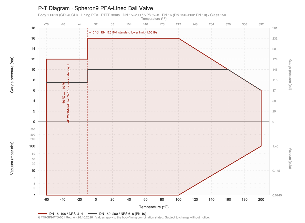
Every GFT9 valve carries one P-T diagram. It shows the pressure the complete valve — body, lining, ball or disc, seals — may carry at a given temperature.
Points on or inside the red line are permitted. The line is a coincident limit (pressure and temperature together), and you may interpolate linearly between the breakpoints. Pressures are gauge pressures. Below the zero line the same diagram shows the permissible vacuum in mbar absolute.
Example: Spheron9 P-T sheet (PDF) →
Why PFA
Two Limits Make One Envelope
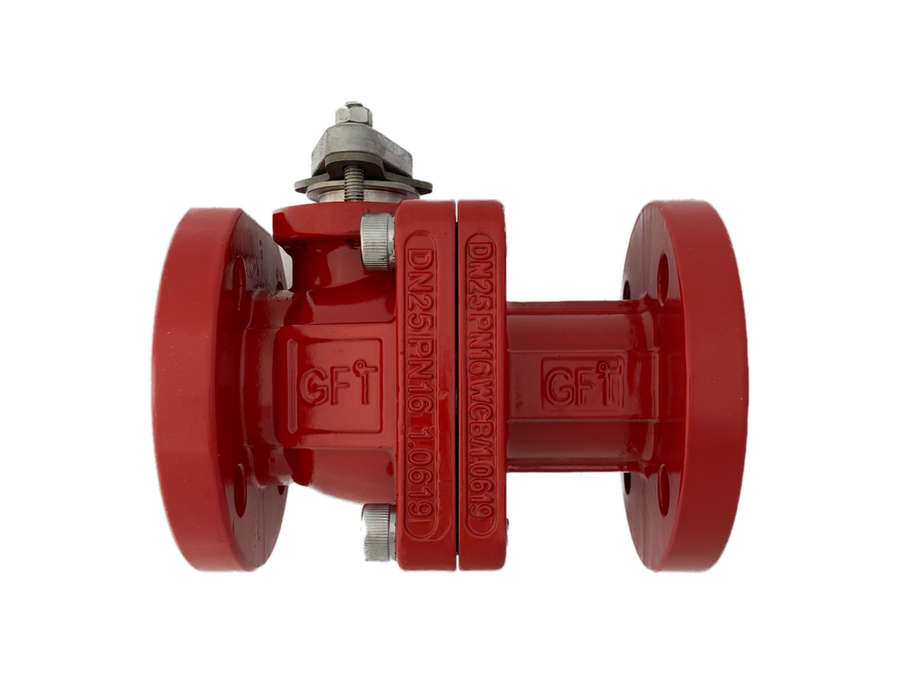
The body limit is the pressure rating of the cast body: PN 16 (EN 1092-1) or Class 150 (ASME B16.5), as marked on the type plate, designed and tested to EN 12516 and the Pressure Equipment Directive. Our standard body is cast carbon steel 1.0619 (GP240GH); stainless castings (1.4408) on request. DN 150 and DN 200 valves are PN 10.
The lining limit comes from testing. PFA itself is good for 260 °C continuous, but a lined valve is limited by what moves and seals inside it: PTFE balls, seats and diaphragms creep under load as temperature rises, permeation through any fluoropolymer increases with temperature, and the liner expands about ten times more than the steel around it. That is why lined valves are published to 150–200 °C, not 260 °C.
16 bar to 100 °C, then down to 6 bar at 200 °C. Every GFT9 PN 16 valve carries its full 16 bar from −10 °C to 100 °C. Above 100 °C the lining system takes over and the permissible pressure falls in a straight line to 6 bar at 200 °C — for example 13 bar at 130 °C, 10 bar at 160 °C, 8 bar at 180 °C. DN 150 and DN 200 valves are PN 10: 10 bar up to 160 °C, where the lining line is reached, then the same decline. The swing check valve (wafer body) keeps PN 16 on all sizes.
Component limits. The sight glass stops at 150 °C (borosilicate glass), the strainer with ETFE basket at 150 °C — with a pure PTFE basket or another mesh material it goes to 200 °C like the other valves.
Two lines with their own rating. The diaphragm valve is rated per size — DN 15–50 16 bar, DN 65–100 10 bar, DN 125–150 7 bar to 100 °C, then down to 10.5 / 6 / 4 bar at its 150 °C upper limit (Membron9 P-T sheet). The butterfly valve is PN 10 on all sizes, because its lug bodies are tapped PN 10: 10 bar to 160 °C, then down to 6 bar at 200 °C; DN 500–600 6 bar (Papilon9 P-T sheet).
Applications
Low Temperature, Vacuum and a Worked Example
Low temperature: −10 °C standard, −60 °C with reduced pressure
The European body tables start at −10 °C for cast carbon steel. The Pressure Equipment Directive asks for proven toughness at the lowest operating temperature (27 J Charpy-V, Annex I 7.5). Below −10 °C we apply AD 2000-Merkblatt W 10, the German rule for ferrous materials at low temperature: with the permissible pressure limited to 75 % of the full rating, cast steel 1.0619 is released down to −60 °C (stress category II). On a PN 16 valve that is the 12 bar block from −60 to −10 °C you see on the diagram. Stainless castings (1.4408) keep their full rating to −60 °C.
Vacuum
All GFT9 lined valves are vacuum-tight: the PFA lining is transfer-moulded into the body and mechanically locked in dovetail grooves, so it cannot detach under vacuum. The diagram shows the permissible vacuum on a logarithmic axis: full vacuum (1 mbar abs) up to 100 °C, then a straight line on that axis to 100 mbar abs at 200 °C (about 10 mbar abs at 150 °C).
Worked example
Design conditions −30 °C to +160 °C, −1 to +9.5 bar g, on a DN 100 PFA-lined check valve with 1.0619 body: −30 °C / 9.5 bar is inside the envelope (12 bar permitted down to −60 °C); 160 °C / 9.5 bar is inside too (10 bar permitted at 160 °C); full vacuum is permitted up to 100 °C and about 15 mbar abs at 160 °C — if full vacuum and 160 °C occur together, that point is to be checked with the plant. The valve fits the design conditions.
What the diagram does not cover
Flange bolting and gaskets of the piping; water hammer; fluids that attack PFA (molten alkali metals, fluorine, some halogenated solvents at high temperature — see the chemical resistance guide); ice formation below 0 °C.
Products
P-T Diagrams per Product Line


Check Valves — Prohibron9 · Vibron9
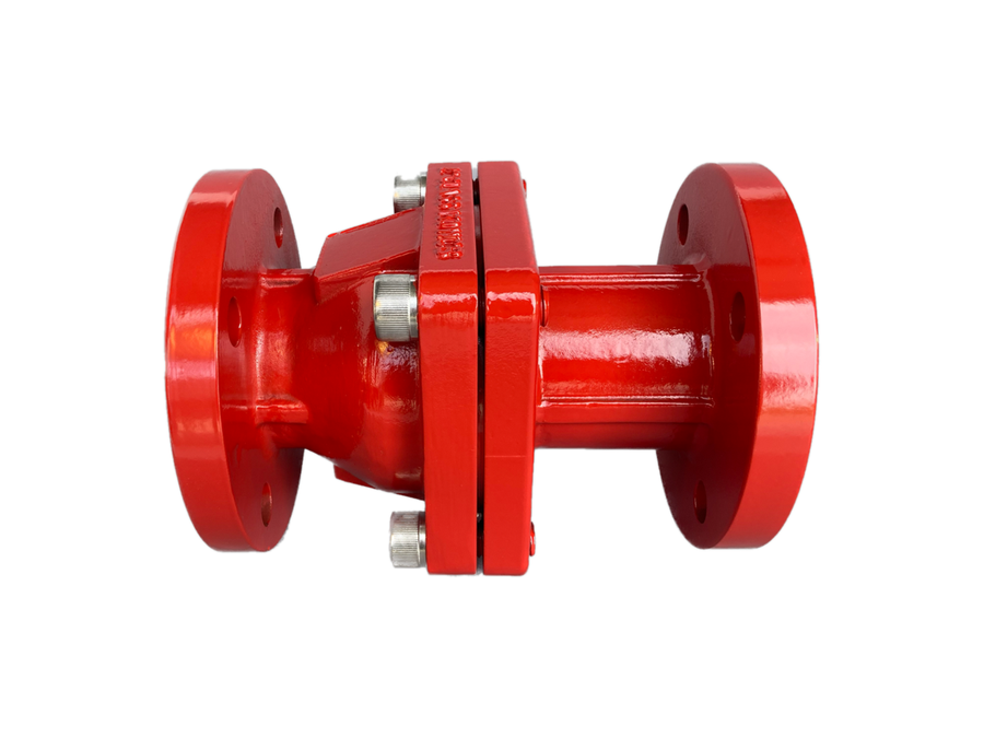
Same envelope. Ball check valve DN 150–200: PN 10; swing check valve PN 16 on all sizes DN 40–400. Prohibron9 P-T sheet (PDF) · Vibron9 P-T sheet (PDF)

Strainer and Sight Glass — Purion9 · Videron9
Strainer: 150 °C with ETFE basket, 200 °C with PTFE basket. Sight glass: 150 °C (glass). Purion9 P-T sheet (PDF) · Videron9 P-T sheet (PDF)

Control and Sample Valves — Imperium9 · Provaron9
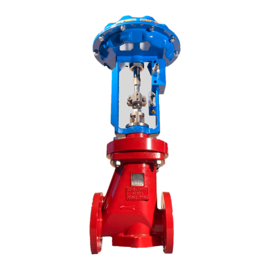
Control valve: heavy-duty bellows 16 bar, standard bellows 10 bar to 160 °C. Sample valve: same envelope as the ball valve. Imperium9 P-T sheet (PDF) · Provaron9 P-T sheet (PDF)
Quality
The Rating Basis Behind Every Diagram
- −60 … −10 °C: 12 bar g (PN 10 sizes 7.5 bar g) — AD 2000-Merkblatt W 10, stress category II (≤ 75 % of the rating), 1.0619 cast body with EN 10204 3.1 certificate.
- −10 … 100 °C: 16 bar g (PN 10 sizes 10 bar g) — pressure rating as on the type plate; shell design to EN 12516; PED 2014/68/EU.
- 100 … 200 °C: linear to 6 bar g at 200 °C — PFA lining system, manufacturer limit (PN 10 sizes: 10 bar g to 160 °C, then the same line).
- Vacuum: 1 mbar abs to 100 °C, then to 100 mbar abs at 200 °C — lining transfer-moulded and anchored in dovetail grooves.
- Every valve pressure-tested in Germany to DIN EN 12266-1 before delivery.
Check Your Design Conditions With Us
Send us the medium, the pressure and temperature range — including vacuum and the lowest temperature — and the size. We check the point against the diagram and send the customer P-T sheet for your documentation.
Email: sales@gft9.shop Phone: +49 2152 9148591