Installation and operating manual

PFA Lined Ball Valve

Spheron9 · transport, installation, operation and maintenance — read before you start.

Document
GFT9-SPI-UM-001
Revision
Rev. L · 2026-11-07
Language
English
Manufacturer
GFT9 · Kempen, Germany
PFA Lined Ball Valve

1 Technical Data

1.1 Manufacturer Information

GFT9
Hooghe Weg 16, 47906 Kempen, Germany
Email: sales@gft9.shop
Web: https://gft9.shop
Phone: +49 2152 9148591

1.2 Product Overview

Parameter Value
Name Spheron9
Operational characteristics On / Off
Design norm DIN | ANSI
Size DN 15-200 | NPS ½"-8"
Flange dimensions EN 1092-1 (PN 16, form B1) | ASME B16.5 (Class 150, RF)
Face to face dimensions EN 558 Series 1 (PN) | ASME B16.10 (Class)
Actuator EN ISO 5211. Standard set-up: actuator flange = valve flange — F05 (DN 15–25), F07 (DN 32–50), F10 (DN 65–100), F12 (DN 125–150); DN 200 on request. Bridge and coupling made in-house.
Lining PFA, PFA/AS (antistatic) — FEP, PFA/UP, PVDF, UHMW-PE on request
Body 1.0619 (A216 WCB), 1.4408 (CF-8M); 1.4409 on request
Pressure 16 bar to 100 °C, 6 bar at 200 °C · DN 150–200 / NPS 6–8: PN 10 · full vacuum (1 mbar abs) to 100 °C · see P-T diagram
Temperature range −60 °C … +200 °C — below −10 °C: 12 bar (1.0619, AD 2000 W 10), full rating with 1.4408 · see P-T diagram. TA-Luft certification valid −20 °C to +180 °C
Custom Actuation, Stem Extension, Heating Jacket, Lock
Quality 100 % per valve to DIN EN 12266: shell 24 bar, shell and seat tightness 6 bar; EN 10204/3.1. 15 kV spark test on request
Certificates EU Pressure Equipment Directive 2014/68/EU (Module A2, notified body 0035; CE marking from DN 25), German Clean Air Act (TA-Luft 8/2021): class BH to DIN EN ISO 15848-1, DN 10–150 / NPS ½"–6", −20 °C to +180 °C

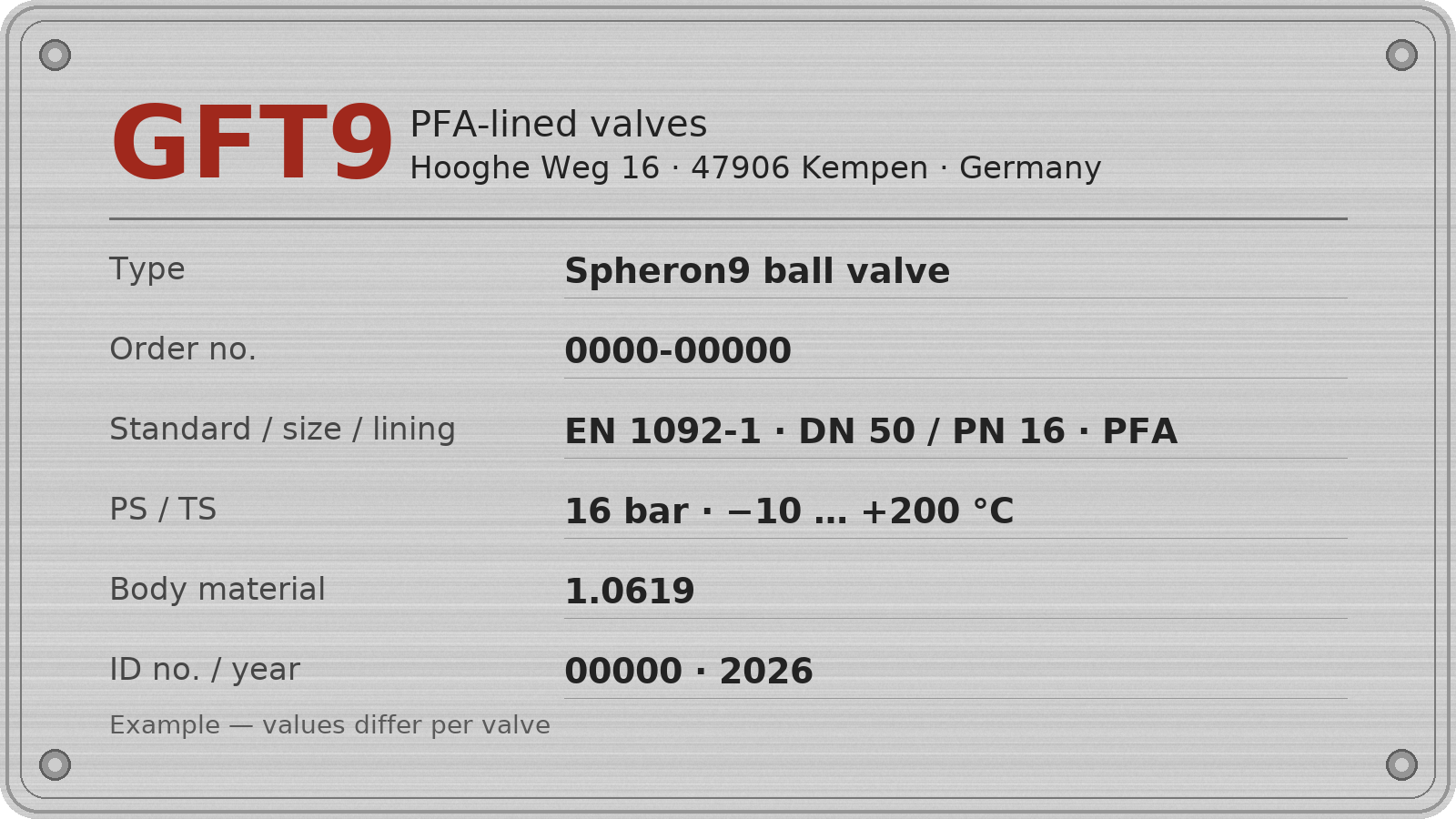
1.3 Type plate, conformity and body markings

GFT9_Example_Nameplate

Type Plate
The stainless steel name plate is permanently riveted to the body. If the operator adds their own marking, they must make sure that the valve is suitable for the application concerned.

Body identification:
In accordance with DIN EN 19 and AD 2000 A4, the body is marked with:

  • Nominal size
  • Pressure rating
  • Body material
  • Manufacturer's mark
  • Melt number/Foundry identification
  • Foundry date

1.4 Weight DIN | ANSI

Weights are listed with the dimensions in Section 10. They are indicative; accurate weight on request.

1.5 Screws: Tightening Torque

Grease all screws and tighten them in diametrically opposite order!
The tightening torques stated for pipe screws and body screws must not be exceeded. An exception is described in Section 8, under 'Flange connection valve/pipe is leaking'. Recommended tightening torques are listed below.

1.5.1 Pipe Screws DIN | ANSI

DIN Pipe Screws
Size Screws Tightening Torque [Nm] — greased
DN 15 4 x M12 6
DN 20 4 x M12 8
DN 25 4 x M12 10
DN 32 4 x M16 10
DN 40 4 x M16 20
DN 50 4 x M16 26
DN 65 4 x M16 26
DN 80 8 x M16 25
DN 100 8 x M16 35
DN 125 8 x M16 55
DN 150 8 x M20 65
DN 200 12 x M20 100
ANSI Pipe Screws
Size Screws Tightening Torque [in-lb / Nm] — greased
NPS ½" 4 x ½“ 45/5
NPS ¾" 4 x ½“ 55/6
NPS 1" 4 x ½“ 70/8
NPS 1½" 4 x ½“ 135/15
NPS 2" 4 x ⅝“ 220/25
NPS 3" 4 x ⅝“ 400/45
NPS 4" 8 x ⅝“ 310/35
NPS 6" 8 x ¾“ 710/80
NPS 8" 8 x ¾“ 1020/115

1.5.2 Body screws DIN | ANSI

DIN Body Screws
Size Screws Tightening Torque [Nm / in-lb] — greased
DN 15 4 x M12 35/310
DN 20 4 x M12 35/310
DN 25 4 x M12 35/310
DN 32 4 x M12 35/310
DN 40 4 x M16 45/398
DN 50 4 x M16 45/398
DN 65 4 x M16 45/398
DN 80 8 x M16 50/442
DN 100 8 x M16 60/531
DN 125 8 x M20 150/1330
DN 150 8 x M20 150/1330
DN 200 12 x M24 175/1549
ANSI Body Screws
Size Screws Tightening Torque [in-lb / Nm] — greased
NPS ½" 4 x M12 310/35
NPS ¾" 4 x M12 310/35
NPS 1" 4 x M12 310/35
NPS 1½" 4 x M16 398/45
NPS 2" 4 x M16 398/45
NPS 3" 8 x M16 442/50
NPS 4" 8 x M16 531/60
NPS 6" 8 x M20 1330/150
NPS 8" 12 x M24 1549/175

1.6 Actuation

DIN Actuation Torque
Size M at Δp 16 bar [Nm]M max. admissible [Nm]
DN 15 1270
DN 20 1270
DN 25 1570
DN 32 on requeston request
DN 40 30210
DN 50 36210
DN 65 on requeston request
DN 80 96420
DN 100 204420
DN 125 on requeston request
DN 150 on request1000
DN 200 on requeston request
ANSI Actuation Torque
Size M at Δp 16 bar [Nm]M max. admissible [Nm]
NPS ½" 1270
NPS ¾" 1270
NPS 1" 1570
NPS 1½" 30210
NPS 2" 36210
NPS 3" 96420
NPS 4" 204420
NPS 6" on request1000
NPS 8" on requeston request

Guide values for the one-piece PFA-lined ball-stem, greased, water 20 °C. Other media, temperatures and long standstill can need higher torque. The max. admissible torque never exceeds the rating of the EN ISO 5211 flange. Two-piece version with ceramic ball (DN 15–20): actuation torque on request.

1.6.1 Actuator connection (standard set-up)

SizeNPSValve flangeBridge HB [mm]HA [mm]Actuator flangeDriveCoupling L [mm]
DN 15NPS ½"F0560on req.F05□1475
DN 20ᵃNPS ¾"F0560on req.F05□1475
DN 25NPS 1"F0560112F05□1475
DN 32ᵃ—F0760on req.F07□2279
DN 40NPS 1½"F0760130F07□2279
DN 50NPS 2"F0760139F07□2279
DN 65ᵃ—F1080on req.F10□27102
DN 80NPS 3"F1080201F10□27102
DN 100ᵃNPS 4"F1080210F10□27102
DN 125ᵃ—F12100on req.F12□27121
DN 150NPS 6"F12100on req.F12□27121
DN 200NPS 8"on request

HB bridge height, valve top flange to actuator flange face · HA flow axis to actuator flange face (sizes with casting model; others on request) · drive = coupling square into the actuator · ᵃ assigned by size group

This is the standard set-up GFT9 proposes. Bridges and couplings are made in-house: other actuator flanges and bridge heights within the physical limits are available on request, e.g. DN 40–50 with F10 on a bridge of 80 mm, DN 65–100 with F12 on 100 mm. Actual values and execution are to be checked on the valve supplied.

1.7 Pressure Temperature Diagram

Ball Valve — pressure-temperature diagram

P-T diagram with vacuum range: 16 bar −10 … 100 °C, linear to 6 bar at 200 °C · DN 150–200 / NPS 6–8: PN 10 · −60 °C at 12 bar (AD 2000-Merkblatt W 10) · one diagram for 1.0619, 1.4408 and 1.4409 bodies · full vacuum (1 mbar abs) to 100 °C

2. Notes on safety

Read this manual before installing and commissioning the valve. It contains the essential instructions for installation, operation and maintenance.
Keep the manual where the valve is in use, so that staff can refer to it at any time.
For use in potentially explosive atmospheres, also follow Section 3.
Only qualified personnel may install, operate and service the valve.
The operator must define the staff's responsibilities and authority and how the staff are supervised.

Every warning and sign on the ball valve itself must be followed and kept fully legible.
Disregarding these safety instructions can void all claims for damages.

It can also lead, for example, to the following hazards:

  • Loss of essential functions of the valve or plant.
  • Danger to persons from electrical, mechanical and chemical effects.
  • Harm to the environment from escaping hazardous substances.
Hazard_Sign_PFA_Lined_Valve_Manual

General hazard symbol!
Danger to persons.

Information_Sign_PFA_Lined_Valve_Manual

Safety symbol!
Disregarding this note can endanger the ball valve and its function.

2.1 Intended use

GFT9 ball valves are on/off valves designed to pass and shut off fluids. They are pressure-containing components as defined by the Pressure Equipment Directive (PED).

The Spheron9 is a two-way on/off valve. It is not intended for throttling or for operation in an intermediate position, see Section 7.2.
For the installation position, see Section 6.2.
The valves are suitable for non-boiling liquids of group 1 in acc. with the Pressure Equipment Directive (PED). Solids in the medium can increase wear, damage the sealing faces or shorten the service life of the valve.

If the operating conditions are to differ from those the valve was ordered for, the operator must carefully check that design, materials and accessories still suit the new application. (Consult the manufacturer.)

2.2 For the customer / operator

The operator is responsible for ensuring that:

  • hot or cold valve parts are guarded against accidental contact
  • the valve is correctly installed in the pipeline
  • flow velocities in continuous service stay within the normal limits for the line.
  • an appropriate collection system is used to contain drip leaks/leaks locally and harmlessly.

These points are not the manufacturer's responsibility.

The design does not take seismic loads into account.

Fire protection to DIN EN ISO 10497 cannot be provided, because the lining and other components are made of plastic.

2.3 Improper operation

Safe and reliable operation depends on using the valve only as described under Intended use (Section 2.1).

Hazard_Sign_PFA_Lined_Valve_Manual

The valve is delivered with flange caps fitted. They keep dirt off the plastic surfaces and protect them from mechanical damage. Remove them only immediately before installation.

3. Use in potentially explosive atmospheres

The valve has no electrical parts and no drive of its own (an actuator is an attachment). Its surface temperature is determined by the medium (and, on heated valves, by the heating medium). The valve carries no ATEX marking.

This manual does not give a general approval for use in potentially explosive atmospheres. Whether the valve may be used in such an area is decided for the specific application, in the operator's own assessment of the zone, the gas or dust group, the temperature class and the electrostatic behaviour of the medium.

GFT9 supports this assessment for a concrete application. On request we provide the design data needed for it — materials, lining type (standard or antistatic), earthing path, exposed non-conductive surfaces — and review the case with you. Contact: sales@gft9.shop.

Points the assessment must cover (from experience with lined valves; not a complete list):

  • Earthing of the valve, e.g. tooth lock washers under the pipe screws or an earthing cable (Section 6, Grounding).
  • Chargeable media (conductivity below 10⁻⁸ S/m): charge can build up on a standard lining; an antistatic lining (PFA/AS: surface resistance below 10⁹ Ω, leakage resistance below 10⁶ Ω) leads it away. With a standard lining the valve must stay completely filled or the atmosphere inside must be inerted; non-antistatic parts can limit the permitted zone and gas group.
  • Exposed non-conductive surfaces, e.g. lining at the flange faces or a sight-glass window.
  • Medium temperature and heating-medium temperature against the temperature class.
  • Actuators, positioners, limit switches, solenoid valves, sensors and heating jackets: their own explosion-protection conformity, per their manuals.
  • Abrasive media and dust deposits on the outside: inspection and cleaning intervals.
  • Plastic-lined valves must not be used with carbon disulfide.
  • Hand-operated as standard; an actuator is an attachment with its own conformity.

WARNING — Ignition from improper use. Overheating, electrostatic charge or sparks can arise if the valve is used outside its intended use. → Use the valve only as described in this manual and as confirmed in the assessment for your application.

4. Safety note for TA Luft (Clean Air Act) versions

A TA Luft certificate is held for the Spheron9 ball valve. For other valves a TA Luft version is available on request. Any TA Luft certificate or manufacturer declaration is valid only if these operating instructions have been read and are followed.

  • Maintain the valve at regular intervals, check that the bolted connections are tight and retighten them where necessary.

5. Transport, storage and disposal

Handle the goods carefully in transit. Protect the valve from knocks and impacts while it is being transported.

Immediately on receipt, check that the consignment is complete and free of transport damage.

Take care not to damage the protective paint coat.

Hazard_Sign_PFA_Lined_Valve_Manual

Carry out all transport work in line with recognised good engineering practice and the accident prevention regulations.

Information_Sign_PFA_Lined_Valve_Manual

The valve is delivered with flange caps fitted. They keep dirt off the plastic surfaces and protect them from mechanical damage. Remove them only immediately before installation.

5.1 Storage

Valves that are not installed straight away must be stored correctly.
Store them in a dry, well-ventilated room free of vibration, at a temperature that is as constant as possible.
Keep elastomer parts out of UV light.
As a rule, the valves should not be stored for more than 10 years.

5.2 Return consignments

A safety information sheet / general safety certificate stating the field of application must always be enclosed with any return consignment.
Contact the Manufacturer for more Information in that regard.
The safety precautions and decontamination measures must be stated.

Hazard_Sign_PFA_Lined_Valve_Manual

Valves that have handled aggressive or toxic media must be rinsed and cleaned before they are returned to the manufacturer's works

5.3 Disposal

Parts of the valve may carry medium residues that are harmful to health and the environment; cleaning alone is therefore not enough.

Hazard_Sign_PFA_Lined_Valve_Manual

The medium can injure people and harm the environment!

Wear suitable personal protective equipment for all work on the valve.
Before disposing of the valve:

  • Collect any escaped medium or other substances and dispose of them according to local regulations.
  • Neutralise medium remaining in the valve.
  • Sort the valve materials by type (plastics, metals, etc.) and dispose of each according to local regulations.

6. Installation

Check the valve for transport damage on receipt. Do not install a damaged ball valve.

  • Clean the valve and the adjoining pipework thoroughly before installation, removing all dirt and in particular hard particles.
  • Install the valve free of stress between aligned pipes, and tighten the bolts to the correct torque.
  • The lever must move freely (deadman's position).
Hazard_Sign_PFA_Lined_Valve_Manual

Lock out remote-controlled actuators so that they cannot start unexpectedly.

6.1 Flange caps and gaskets

Leave the flange caps on until the valve is about to be installed.

If the plastic sealing faces are at particular risk of damage, for example from metal or enamelled mating flanges, PTFE-lined gaskets with metal inserts are recommended. Contact the Manufacturer for further discussion.

6.2 Direction of flow and installation position

The valve can be installed in any position and independent of the flow direction.

Valves with an additional relief bore (cavity-free ball/stem unit, Al₂O₃ ball) carry a flow-direction arrow: install them with the bore on the p1 side (see Sections 9.2 and 9.4).

6.3 Grounding

The valve must be grounded. The simplest way is to fit tooth lock washers under the pipe screws. Fit them under one pipe screw on each flange.

Upon customer request a set screw M6 is attached to each flange with a hex nut and washer as an additional earthing connection.

If this is not possible, grounding must be provided another way, e.g. with an earthing cable.

6.4 Test pressure

The test pressure PT must not be higher than 1.5 x PS(PN), with PS(PN) as stated in the valve marking.

7. Operation

7.1 Initial commissioning

The valves are normally leak-tested with air or water at the factory. Check the cover screws before commissioning. For tightening torques, see Section 1.5.2!

When the valve reaches operating pressure and temperature for the first time, retighten all bolted joints to prevent leaks. For tightening torques, see Section 1.5.1.

Hazard_Sign_PFA_Lined_Valve_Manual

Unless dry delivery was agreed, some water may remain in the flow passage of the valve. This water may react with the medium.

7.2 Improper operation and their consequences

  • Prevent the medium from crystallising, for example by heating. Damage to the seat rings or the ball stem unit would be inevitable. In extreme cases a leak or blocking may occur.
  • Solids in the medium increase wear.
  • The ball valve is an on/off valve and shall not be operated in an intermediate position. Damage to the seat rings or the ball/stem unit or Al2O3-ball and stem could occur.
  • If the ball blocks, do not apply force as the ball/stem may break if the max.adm. torque is exceeded
  • Operating under cavitation increases wear.
  • Operating outside the pressure-temperature diagram can damage the valve.
  • Do not transport the valve using the lever.
  • Do not extend the lever, as this can cause damage.

7.3 Shutdown

Comply with the local regulations when dismantling the valve!

As soon as the valve has been removed, fit flange caps to protect the flanges from mechanical damage. See also Section 6.1.
Lock out remote-controlled actuators so that they cannot start unexpectedly.

Hazard_Sign_PFA_Lined_Valve_Manual

Before undoing the flange connection, make sure that the plant has been depressurised and emptied!

Hazard_Sign_PFA_Lined_Valve_Manual

Clean the valve thoroughly before any repair. Medium can remain inside even after correct draining and flushing.

8. Malfunctions

Flange connection ball valve/pipe is leaking:

  1. Retighten the flange screws to the torque given in Section 1.5.1. If the joint still leaks, the screws may be tightened up to 10% above the recommended torque.
  2. If the leak persists, dismantle the valve and inspect it.

Flange connection main body/body end piece is leaking:

  • Retighten the body screws crosswise to the torque given in Section 1.5.2. If the leak persists, see paragraph “Flange connection ball valve/pipe is leaking".

Packing is leaking:

  • Retighten the packing nuts alternately until there is no gap between packing gland follower (Pos. 10) and spring gland follower (Pos. 8), see Section 9.2.2. Do not tighten beyond the closed gap.
  • If the leak persists, dismantle and inspect the packing bellows (Pos. 3), see Section 9.3.2.

Ball valve does not operate or the actuator stalls:

  1. Is power reaching the actuator?
  2. Is the solenoid valve, if fitted, connected correctly?
  3. Are there foreign objects in the valve?
  4. Manual valve: see “Operating torque higher than stated in Section 1.6”. Do not apply force — the ball/stem may break if the max. admissible torque is exceeded (Section 7.2).
  5. Actuated valve: check the supply and the directional control valve, and check that the coupling is seated on the stem (Section 9.4.3). Check the actuator against Sections 1.6 and 1.6.1: the actuation torque rises with other media, low temperature and long standstill.

The ball no longer closes completely:

  1. Is the stem deformed?
  2. Is the coupling worn?
  3. With a worm gear or actuator, check whether the end stops can be re-adjusted. The operating manuals of the gear and actuator manufacturers contain accurate instructions.
  4. Try to get the ball valve working again by moving the lever to and from.
  5. Check the 90° travel stop between lever and gland follower: if it is worn or damaged, the ball can turn past its end position.
  6. If actuation is not possible with the max. admissible actuating torque as per Section 1.6, dismantle ball valve and inspect individual components.
  7. If the ball reaches the closed position and the valve still passes, the seat rings (Pos. 4) or the ball are worn or damaged: replace the seat rings (Section 9.3.1) and inspect the lining of the ball (Pos. 6); replace the ball/stem unit if the lining is damaged.

In General: Never apply force to the lever or use an extension.

Operating torque higher than stated in Section 1.6:

  1. Never apply force to the lever or use an extension; if the ball blocks, the ball/stem may break if the max. admissible torque is exceeded (Section 7.2).
  2. Crystallised or solidified medium in the valve: prevent the medium from crystallising, for example by heating (Section 7.2). Flush the valve or heat it to dissolve deposits if the process allows.
  3. Check the packing: the packing nuts must not be tightened beyond the point where the gap between packing gland follower (Pos. 10) and spring gland follower (Pos. 8) is closed (Section 9.2.2).
  4. Actuated valves: check the fits of the coupling, bracket and actuator (Section 9.5, Step 2).
  5. If the torque still exceeds the value in Section 1.6, dismantle the ball valve and inspect the seat rings (Pos. 4), see Sections 9.1 and 9.3.

9. Maintenance

Before you start

  1. Make sure that the plant is depressurised and emptied before undoing any connection (Section 7).
  2. Lock out remote-controlled actuators so that they cannot start unexpectedly (Section 7.3).
  3. Clean the valve thoroughly before starting any repair work. Medium can remain inside even after correct draining and flushing (Section 7). Wear suitable personal protective equipment for all work on the valve (Section 5.3).
  4. As soon as the valve is out of the line, fit flange caps to protect the flanges from mechanical damage (Section 6.1).
  • Repairs may only be carried out by qualified staff with suitable tools.
  • The exploded view in Section 11 shows the position, name and item number of every part of the valve.
  • Fitting aids and actuator parts used in the steps below (mounting sleeve, additional disc, plug, bracket, coupling) are not shown in the parts list; order them from GFT9 with the valve identification.
  • When ordering spare parts, quote all data from the valve identification.
  • Use genuine GFT9 spare parts only.
  • To avoid leaks, check the bolted connections regularly, at intervals suited to the operating conditions.
  • For tightening torques, see Section 1.5

Hazard_Sign_PFA_Lined_Valve_Manual

Make sure that when working on the ball valve it is drained. See also Section 7.3

9.1 Disassembling ball valve with ball/stem unit

9.1.1 Ball valve with lever

Step 1:
Remove lever.

Step 2:
Take out grounding spring washers.

Step 3:
Dismantle packing gland follower and spring gland follower.

Step 4:
The thrust ring, packing bellows and retaining washer are one unit and it is levered out using 2 screwdrivers.

Step 5:
Undo screw connection body end piece / main body. Remove body end piece

Step 6 (Only DN200):
Carefully slide the mounting sleeve (fitting aid, available from the manufacturer) up to the stop into the shaft passage of the main body. Carefully slide out the mounting sleeve.

Step 7:
Remove ball/stem unit (Pos. 6) in closed position. Make sure that you do not damage the body lining, then carefully remove seat rings.

9.1.2 Packing Bellows

Step 1:
Remove retaining washer.

Step 2:
Separate thrust ring and packing bellows by pushing them apart.

9.1.3 Ball valve with actuator

Step 1:
Remove actuator and coupling.

Step 2:
Dismantle packing gland follower and spring gland follower.

Step 3:
Remove bracket.

Further dismantling is performed as described in Section 9.1.1 and 9.1.2

9.2 Assembly

Prior to assembly all parts are to be cleaned and the plastic-lined parts checked for damage.
Step 1:
Insert seat rings in the main body and body end piece.
Step 2 (Only DN200):
Carefully slide the mounting sleeve (fitting aid, available from the manufacturer) up to the stop into the shaft passage of the main body.
Step 3:
Mount ball/stem unit in closed position. Make sure that you do not damage the body lining.
NOTE: An additional bore in the ball/stem unit, e.g. to ensure it is cavity-free,must lie on the p1 side in the closed position.
Step 4 (Only DN200):
Carefully slide out the mounting sleeve.

Step 5:
Mount body end piece. Tighten the greased housing screws cross over with a tightening torque according to Section 1.5.2

9.2.1 Packing bellows

Step 1:
Press thrust ring into packing bellows. Install retaining washer (Pos. 12).
Step 2:
Press unit into main body.
Step 3:
Press in grounding spring washer.

9.2.2 Ball valve with lever

Step 1:
Mount spring gland follower (in DN 80, 100, 150, and 200 are 2 spring gland followers (Pos. 8)) and packing gland follower. Tighten packing nuts until there is no gap between packing gland follower (Pos. 10) and spring gland follower. See Section 11 (Pos. 8, Pos. 10). Do not tighten beyond the closed gap.
Step 2:
Seal any tapped bores still open with plugs. Then, Mount lever.

9.2.3 Ball valve with actuator

Step 1:
Mount spring gland follower (Pos. 8) (in DN 80, 100, 150 and 200 are 2 spring gland followers (Pos. 8)) and packing gland follower (Pos. 10). Tighten packing nuts until there is no gap between packing gland follower and spring gland follower.
See Section 11 (Pos. 8, Pos. 10). Do not tighten beyond the closed gap.
Step 2:
Mount the mounting bracket with the opening at right angles to the direction of flow. See the exploded view in Section 11.
Step 3:
Mount the coupling and the actuator. The actuator interface conforms to ISO 5211; the coupling and bracket must match the flange size (F05, F07, F10, F12) of the actuator being fitted. Standard bridge and coupling per nominal size: see Section 1.6.1. Observe the actuator position in accordance with the actuator operating manual.
Step 4:
Observe the ball/stem position in accordance with the position of the actuator.

9.3 Dismantling ball valve with ball and stem

It is possible with a ball valve with ball and stem to replace the seat rings and ball without dismantling the entire ball valve.
It is equally possible to remove the packing gland follower, spring gland follower and packing insert without dismantling the body.
The entire ball valve must merely be taken apart to remove the stem. For the exploded view, see Section 11.

9.3.1 Ball and seat rings

Step 1:
Move ball (Pos. 6) into the 'closed' position.
Step 2:
Undo body nuts and bolts and remove body end piece.
Step 3:
Remove ball from the main body by swivelling it.
Step 4:
Consequently, remove seat rings from the main body and body end piece and replace.

9.3.2 Packing bellows

Step 1:
Remove lever. Then, safely dismantle packing gland follower and spring
gland follower.
Step 2:
Take out grounding spring washer.
Step 3:
The thrust ring, packing bellows and retaining washer
are one unit and it is levered out using 2 screw-drivers.
Step 4:
Remove retaining washer. Following, separate thrust ring and packing bellows by pushing them apart.

9.3.3 Ball valve with actuator

Step 1:
Remove actuator and coupling. Then, dismantle packing gland follower and spring gland follower and remove bracket.
Further dismantling is performed as described in Sections 9.3.1, 9.3.2 and 9.3.4.

9.3.4 Stem

Step 1:
Dismantling as described in section 9.3.1.
Step 2:
Remove ball and stem in closed position. Make sure that you do not damage the body lining.
Step 3:
Swivel ball from stem.

9.4 Assembly

Prior to assembly all parts are to be cleaned and the plastic-lined parts checked for damage!
Step 1:
Insert seat rings in the main body and body end piece.
Step 2:
Insert stem from inside into the main body. In the case of DN 150 and 200 with an additional disc.
Step 3:
Move stem into the 'closed' position and swivel ball into the stem. Any pressure
relief or drain bore must lie on the p1 side in the "off" position. See also section 6.2.
Step 4:
Mount body end piece. Tighten the greased housing screws cross over with a tightening torque according to Section 1.5.2

9.4.1 Packing bellows

Step 1:
Press thrust ring into packing bellows and install retaining washer.
Step 2:
Press unit into main body and insert grounding spring washer.

9.4.2 Ball valve with lever

Step 1:
Mount spring gland follower (in DN 80, 100, 150 and 200 are 2 spring gland followers) and packing gland follower. Tighten packing nuts until there is no gap between packing gland follower (Pos. 10) and spring gland follower (Pos. 8). See Section 11. Do not tighten beyond the closed gap.
Step 2:
Seal any tapped bores still open with plugs, then Mount lever.

9.4.3 Ball valve with actuator

Step 1:
Mount spring gland follower (in DN 80, 100, 150 and 200 are 2 spring gland followers) and packing gland follower. Tighten packing nuts until there is no gap between packing gland follower (Pos. 10) and spring gland follower (Pos. 8). See Section 11. Do not tighten beyond the closed gap.
Step 2:
Mount bracket with the opening at right angles to the direction of flow.
Step 3:
Mount the coupling and the actuator. The actuator interface conforms to ISO 5211; the coupling and bracket must match the flange size (F05, F07, F10, F12) of the actuator being fitted. Standard bridge and coupling per nominal size: see Section 1.6.1. Observe the actuator position in accordance with the actuator operating manual.

Step 4:
Make sure that the position of the ball valve with ball and stem, and the position of the actuator are aligned

9.5 Mounting an actuator (standard set-up)

Applies to the conversion from lever to actuator and to fitting your own actuator on a valve delivered with bridge and coupling. Bridge, coupling and actuator flange per Section 1.6.1, drawings in Section 10.3. Everything beyond these steps — air supply or wiring, solenoid valve, limit switch box, positioner, end-stop setting — follows the actuator operating manual.
Step 1:
Lever version only: remove the lever and the plug. The 90° travel stop acts between lever and gland follower; on the actuated valve the end stops of the actuator limit the travel (Step 7).
Step 2:
Check the fits: actuator flange and drive square must match the bridge and coupling of the size (Section 1.6.1). The actuator torque must cover the actuation torque of the duty and must not exceed the max. admissible torque (Section 1.6).
Step 3:
Mount the bridge with the opening at right angles to the direction of flow and screw it to the valve top flange (EN ISO 5211), tightening the screws crosswise.
Step 4:
Slide the coupling onto the two-flat stem drive. It must go on without force and must not press on the stem.
Step 5:
Bring valve and actuator into the same position, e.g. both closed. A spring-return actuator rests in its fail position: set the valve to that position.
Step 6:
Set the actuator onto the bridge so that its drive engages the coupling square, and screw the actuator flange to the bridge crosswise.
Step 7:
Connect the actuator as described in its operating manual, set the end stops so that the ball reaches the fully open and the fully closed position, then cycle the valve several times and check the end positions and the limit switch signals.

9.6 Stem seal after storage or extended standstill

The stem seal is spring-loaded and compensates packing set in service. After long storage the spring travel may be used up and a gap appears between the packing gland follower (Pos. 10) and the spring gland follower (Pos. 8).

Before installation, tighten the packing nuts alternately in small steps until there is no gap between packing gland follower and spring gland follower, then operate the valve once through a full stroke.

Stop once the gap is closed — further tightening raises the operating torque and wears the packing without improving tightness. See Section 9.2.2.

10. Dimensional Drawings

10.1 Dimensional Measurements DIN

Ball Valve — dimensional drawing
Size L1 LH H1 Ød Øk ØD n × ØB Weight (indicative)
DN 15 130 mm 58.5 mm 126 mm 45 mm 65 mm 95 mm 4 x 14 (M12) 8 kg
DN 20 150 mm 58.5 mm 126 mm 58 mm 75 mm 105 mm 4 x 14 (M12) 10 kg
DN 25 160 mm 52 mm 126.5 mm 68 mm 85 mm 115 mm 4 x 14 (M12) 12 kg
DN 32 180 mm 60 mm 126 mm 78 mm 100 mm 140 mm 4 x 18 (M16) 18 kg
DN 40 200 mm 67.5 mm 189 mm 88 mm 110 mm 150 mm 4 x 18 (M16) 20 kg
DN 50 230 mm 80 mm 200 mm 102 mm 125 mm 165 mm 4 x 18 (M16) 25 kg
DN 65 290 mm 77.5 mm 220 mm 122 mm 145 mm 185 mm 4 x 18 (M16) 40 kg
DN 80 310 mm 85.5 mm 259 mm 138 mm 160 mm 200 mm 8 x 18 (M16) 60 kg
DN 100 350 mm 94 mm 267.5 mm 158 mm 180 mm 220 mm 8 x 18 (M16) 80 kg
DN 125 400 mm 124 mm 188 mm 210 mm 250 mm 8 x 18 (M16) 110 kg
DN 150 480 mm 124 mm 212 mm 240 mm 285 mm 8 x 22 (M20) 160 kg
DN 200 600 mm 200 mm 268 mm 295 mm 340 mm 12 x 22 (M20) 265 kg

Indicative weights, in line with body volume. Accurate weight on request: sales@gft9.shop.

10.2 Dimensional Measurements ANSI

Ball Valve — dimensional drawing
Size L1 LH H1 Ød Øk ØD n × ØB Weight (indicative)
NPS ½" 108 mm 55 mm 126 mm 34.9 mm 60.3 mm 88.9 mm 4 x 15.9 8 kg
NPS ¾" 117 mm 55 mm 126 mm 42.9 mm 69.9 mm 98.4 mm 4 x 15.9 10 kg
NPS 1" 127 mm 65 mm 126.5 mm 50.8 mm 79.4 mm 108 mm 4 x 15.9 12 kg
NPS 1½" 165 mm 65 mm 189 mm 73 mm 98.4 mm 127 mm 4 x 15.9 20 kg
NPS 2" 178 mm 80 mm 200 mm 92.1 mm 120.7 mm 152.4 mm 4 x 19.1 25 kg
NPS 3" 203 mm 85 mm 259 mm 127 mm 152.4 mm 190.5 mm 4 x 19.1 60 kg
NPS 4" 229 mm 95 mm 267.5 mm 157.2 mm 190.5 mm 228.6 mm 8 x 19.1 80 kg
NPS 6" 394 mm 125 mm 216 mm 241.3 mm 279.4 mm 8 x 22.2 160 kg
NPS 8" 457 mm 269.9 mm 298.5 mm 342.9 mm 8 x 22.2 265 kg

Indicative weights, in line with body volume. Accurate weight on request: sales@gft9.shop.

10.3 Actuated execution

Actuator mounting, standard set-up — bridge, coupling and actuator envelope, standard actuator connection per size (GFT9-SPI-ACT-001 Rev. B)
Sectional drawing DN 40, actuated execution — bridge F07 → F07 (pos. 20) and coupling □22 (pos. 23), actuator not shown (GFT9-SPI-DS-040-ACT Rev. A)

11. Exploded View and Parts List

Ball Valve — sectional drawing with parts list positions
Pos. Item Material
1, 2, 10 Body / End Flange / Gland Follower 1.0619 (A216 WCB), 1.4408 (CF-8M)
1, 2, 6 Lining Body / Ball Standard: PFA, PFA/AS (antistatic). On request: FEP, PFA/UP, PVDF, UHMW-PE
3 Packing bellows PTFE/TFM, PTFE/AS
4 Seat Rings PTFE/TFM, PTFE/AS, GF PTFE; other seat materials on request
5 Thrust Ring Steel
6 Ball / Stem CD4MCuN
7 Lever 1.0619 (A216 WCB), 1.4408 (CF-8M)
8 Spring Gland Follower Spring Steel
9, 13–17, 19 Bolts, Nuts and Washers Stainless Steel A2, A4, 5.6, o. o. req.
11 Earthing Spring 1.4301
12 Retaining Washer 1.4301

12. Declaration of Conformity

Konformitätserklärung 2014/68/EU
Declaration of Conformity 2014/68/EU

Manufacturer GFT German Fluorolined Technik GmbH, Hooghe Weg 16, 47906 Kempen, Germany
Product Ball Valve
Design 2-piece ball valve, PFA-lined (Spheron9)
Serial number
Size DN 15 – DN 200 | NPS ½" – NPS 8"
EU directive Pressure Equipment Directive 2014/68/EU
Applied technical specifications DIN EN ISO 12100, AD 2000
Conformity assessment procedure Module A2, certificate no. 01 202 640/Ü-18 0002.02
Notified body TÜV Rheinland Industrie Service GmbH, identification no. 0035
Marking CE 0035¹⁾ from DN 25 / NPS 1"

GFT German Fluorolined Technik GmbH declares under its sole responsibility that the product described above meets the essential requirements of the directive and standards listed above.

¹⁾ Smaller sizes must not bear this marking.

Kempen, 03.11.2026

K. Schalm