Installation and operating manual

PFA Lined Strainer

Purion9 · transport, installation, operation and maintenance — read before you start.

Document
GFT9-PUR-UM-001
Revision
Rev. G · 2026-11-07
Language
English
Manufacturer
GFT9 · Kempen, Germany
PFA Lined Strainer

1 Technical Data

1.1 Manufacturer Information

GFT9
Hooghe Weg 16, 47906 Kempen, Germany
Email: sales@gft9.shop
Web: https://gft9.shop
Phone: +49 2152 9148591

1.2 Product Overview

Parameter Value
Name Purion9
Design norm DIN/ISO | ANSI
Size DN 25–150 | NPS 1"-6"
Flange dimensions EN 1092-1 (PN 16) | ASME B16.5 (Class 150, RF)
Face to face dimensions DIN EN 558-1
Strainer basket Material: PTFE or PTFE-Carbon-Composite filter element Mesh: ETFE filter mesh size from 85 to 2000 µm (max. 150°C, for higher temperature, custom mesh provided up to 200°C)
Lining PFA, PFA/AS, PVDF
Body 1.0619, 1.4408, 1.4409, A216 WCB, CF8M, CF3M
Pressure 16 bar to 100 °C, 6 bar at 200 °C · DN 150 / NPS 6: PN 10 · full vacuum (1 mbar abs) to 100 °C · see P-T diagram
Temperature range −60 °C … +150 °C (ETFE basket) / +200 °C (PTFE basket) · 12 bar below −10 °C · see P-T diagram
Quality Body 24bar, Dielectric strength test 20kV
Certificates EU Pressure Equipment Directive 2014/68/EU

1.3 Type plate, conformity and body markings

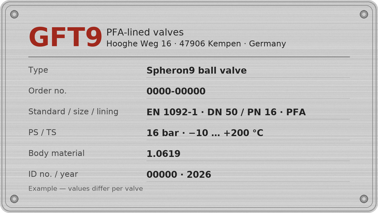
GFT9_Example_Nameplate

Type Plate
The stainless steel name plate is permanently riveted to the body. If the operator adds their own marking, they must make sure that the valve is suitable for the application concerned.

Body identification:
In accordance with DIN EN 19 and AD 2000 A4, the body is marked with:

  • Nominal size
  • Pressure rating
  • Body material
  • Manufacturer's mark
  • Melt number/Foundry identification
  • Foundry date

1.4 Weight DIN | ANSI

Weights are listed with the dimensions in Section 10. They are indicative; accurate weight on request.

1.5 Screws: Tightening Torque

Grease all screws and tighten them in diametrically opposite order!
The tightening torques stated for pipe screws and body screws must not be exceeded. An exception is described in Section 8, under 'Flange connection valve/pipe is leaking'. Recommended tightening torques are listed below.
Pipe flange bolting according to DIN EN 1092-1 PN 16 | ASME B16.5 Class 150.

1.5.1 Pipe Screws DIN | ANSI

DIN Pipe Screws
Size Screws Tightening Torque [Nm] — greased
DN 25 4 x M12 10
DN 50 4 x M16 26
DN 80 8 x M16 45
DN 100 8 x M16 35
ANSI Pipe Screws
Size Screws Tightening Torque [in-lb / Nm] — greased
NPS 1" 4 x ½“ 70/8
NPS 2" 4 x ⅝“ 220/15
NPS 3" 4 x ⅝“ 400/45
NPS 4" 8 x ⅝“ 310/35

1.5.2 Body screws DIN | ANSI

DIN Body Screws
Size Screws Tightening Torque [Nm / in-lb] — greased
DN 25 Top: 4 × stud DIN 938 M12×35 | Bottom: 4 × cyl.-head screw ISO 4762 M12×40/45 50
DN 50 Top: 6 × stud DIN 938 M12×35 | Bottom: 8 × cylinder-head screw ISO 4762 M12×65 50
DN 80 Top: 6 × stud DIN 938 M12×40 | Bottom: 8 × stud DIN 938 M12×45 50
DN 100 Top: 6 × stud DIN 938 M12×45 | Bottom: 8 × hex screw DIN 933 M12×45 50
ANSI Body Screws
Size Screws Tightening Torque [in-lb / Nm] — greased
NPS 1" Top: 4 × stud DIN 938 M12×35 | Bottom: 4 × cyl.-head screw ISO 4762 M12×40/45 442 in-lbs / 50 Nm
NPS 2" Top: 6 × stud DIN 938 M12×35 | Bottom: 8 × cylinder-head screw ISO 4762 M12×65 442 in-lbs / 50 Nm
NPS 3" Top: 6 × stud DIN 938 M12×40 | Bottom: 8 × stud DIN 938 M12×45 442 in-lbs / 50 Nm
NPS 4" Top: 6 × stud DIN 938 M12×45 | Bottom: 8 × hex screw DIN 933 M12×45 442 in-lbs / 50 Nm

1.6 Pressure Temperature Diagram

Strainer — pressure-temperature diagram

P-T diagram with vacuum range: 16 bar −10 … 100 °C, linear to 6 bar at 200 °C (PTFE basket) · ETFE basket to 150 °C · DN 150 / NPS 6: PN 10 · −60 °C at 12 bar (AD 2000-Merkblatt W 10) · one diagram for 1.0619, 1.4408 and 1.4409 bodies · full vacuum (1 mbar abs) to 100 °C

2. Notes on safety

Read this manual before installing and commissioning the valve. It contains the essential instructions for installation, operation and maintenance.
Keep the manual where the valve is in use, so that staff can refer to it at any time.
For use in potentially explosive atmospheres, also follow Section 3.
Only qualified personnel may install, operate and service the valve.
The operator must define the staff's responsibilities and authority and how the staff are supervised.

Every warning and sign on the strainer itself must be followed and kept fully legible.
Disregarding these safety instructions can void all claims for damages.

It can also lead, for example, to the following hazards:

  • Loss of essential functions of the valve or plant.
  • Danger to persons from electrical, mechanical and chemical effects.
  • Harm to the environment from escaping hazardous substances.
Hazard_Sign_PFA_Lined_Valve_Manual

General hazard symbol!
Danger to persons.

Information_Sign_PFA_Lined_Valve_Manual

Safety symbol!
Disregarding this note can endanger the strainer and its function.

2.1 Intended use

GFT9 Purion9 strainers are designed to pass fluids and to filter out particles of a defined grain size. They are pressure-maintaining components as defined by the Pressure Equipment Directive (PED). The strainer separates solid or suspended matter out of the conveyed medium. In this way it protects downstream equipment against the separated material and the damage it would cause.

The valves are suitable for non-boiling liquids of group 1 in acc. with the Pressure Equipment Directive (PED). Solids in the medium can increase wear, damage the sealing faces or shorten the service life of the valve.

If the operating conditions are to differ from those the valve was ordered for, the operator must carefully check that design, materials and accessories still suit the new application (consult the manufacturer).

2.2 For the customer / operator

The operator is responsible for ensuring that:

  • hot or cold valve parts are guarded against accidental contact
  • the valve is correctly installed in the pipeline
  • flow velocities in continuous service stay within the normal limits for the line.
  • an appropriate collection system is used to contain drip leaks/leaks locally and harmlessly.

These points are not the manufacturer's responsibility.

The design does not take seismic loads into account.

Fire protection to DIN EN ISO 10497 cannot be provided, because the lining and other components are made of plastic.

2.3 Improper operation

Safe and reliable operation depends on using the valve only as described under Intended use (Section 2.1).

Hazard_Sign_PFA_Lined_Valve_Manual

The valve is delivered with flange caps fitted. They keep dirt off the plastic surfaces and protect them from mechanical damage. Remove them only immediately before installation.

3. Use in potentially explosive atmospheres

The valve has no electrical parts and no drive of its own (an actuator is an attachment). Its surface temperature is determined by the medium (and, on heated valves, by the heating medium). The valve carries no ATEX marking.

This manual does not give a general approval for use in potentially explosive atmospheres. Whether the valve may be used in such an area is decided for the specific application, in the operator's own assessment of the zone, the gas or dust group, the temperature class and the electrostatic behaviour of the medium.

GFT9 supports this assessment for a concrete application. On request we provide the design data needed for it — materials, lining type (standard or antistatic), earthing path, exposed non-conductive surfaces — and review the case with you. Contact: sales@gft9.shop.

Points the assessment must cover (from experience with lined valves; not a complete list):

  • Earthing of the valve, e.g. tooth lock washers under the pipe screws or an earthing cable (Section 6, Grounding).
  • Chargeable media (conductivity below 10⁻⁸ S/m): charge can build up on a standard lining; an antistatic lining (PFA/AS: surface resistance below 10⁹ Ω, leakage resistance below 10⁶ Ω) leads it away. With a standard lining the valve must stay completely filled or the atmosphere inside must be inerted; non-antistatic parts can limit the permitted zone and gas group.
  • Exposed non-conductive surfaces, e.g. lining at the flange faces or a sight-glass window.
  • Medium temperature and heating-medium temperature against the temperature class.
  • Actuators, positioners, limit switches, solenoid valves, sensors and heating jackets: their own explosion-protection conformity, per their manuals.
  • Abrasive media and dust deposits on the outside: inspection and cleaning intervals.
  • Plastic-lined valves must not be used with carbon disulfide.
  • No moving parts in operation.
  • Fine meshes can charge chargeable liquids more strongly than plain pipe flow (TRGS 727).

WARNING — Ignition from improper use. Overheating, electrostatic charge or sparks can arise if the valve is used outside its intended use. → Use the valve only as described in this manual and as confirmed in the assessment for your application.

4. Safety note for TA Luft (Clean Air Act) versions

A TA Luft certificate is held for the Spheron9 ball valve. For other valves a TA Luft version is available on request. Any TA Luft certificate or manufacturer declaration is valid only if these operating instructions have been read and are followed.

  • Maintain the valve at regular intervals, check that the bolted connections are tight and retighten them where necessary.

5. Transport, storage and disposal

Handle the goods carefully in transit. Protect the valve from knocks and impacts while it is being transported.

Immediately on receipt, check that the consignment is complete and free of transport damage.

Take care not to damage the protective paint coat.

Hazard_Sign_PFA_Lined_Valve_Manual

Carry out all transport work in line with recognised good engineering practice and the accident prevention regulations.

Information_Sign_PFA_Lined_Valve_Manual

The valve is delivered with flange caps fitted. They keep dirt off the plastic surfaces and protect them from mechanical damage. Remove them only immediately before installation.

5.1 Storage

Valves that are not installed straight away must be stored correctly.
Store them in a dry, well-ventilated room free of vibration, at a temperature that is as constant as possible.
Keep elastomer parts out of UV light.
As a rule, the valves should not be stored for more than 10 years.

5.2 Return consignments

A safety information sheet / general safety certificate stating the field of application must always be enclosed with any return consignment.
Contact the Manufacturer for more Information in that regard.
The safety precautions and decontamination measures must be stated.

Hazard_Sign_PFA_Lined_Valve_Manual

Valves that have handled aggressive or toxic media must be rinsed and cleaned before they are returned to the manufacturer's works

5.3 Disposal

Parts of the valve may carry medium residues that are harmful to health and the environment; cleaning alone is therefore not enough.

Hazard_Sign_PFA_Lined_Valve_Manual

The medium can injure people and harm the environment!

Wear suitable personal protective equipment for all work on the valve.
Before disposing of the valve:

  • Collect any escaped medium or other substances and dispose of them according to local regulations.
  • Neutralise medium remaining in the valve.
  • Sort the valve materials by type (plastics, metals, etc.) and dispose of each according to local regulations.

6. Installation

  • Check the valve for transport damage on receipt. Do not install a damaged strainer.
  • Clean the valve and the adjoining pipework thoroughly before installation, removing all dirt and in particular hard particles.
  • Install the valve free of stress between aligned pipes, and tighten the bolts to the correct torque.

6.1 Flange caps and gaskets

Leave the flange caps on until the valve is about to be installed.
If the plastic sealing faces are at particular risk of damage, for example from metal or enamelled mating flanges, PTFE-lined gaskets with metal inserts are recommended. Contact the Manufacturer for further discussion.

6.2 Direction of flow and installation position

Install the valve in the correct direction of flow. An arrow on the valve body shows the direction.
Always install the strainer so that, with the strainer basket removed, it can be drained from the bottom.
If it is installed in the wrong position, performance may drop or the strainer may fail to function.
Observe removal height A in acc. with the drawings in Section 10.1 / 10.2.

6.3 Grounding

The valve must be grounded. The simplest way is to fit tooth lock washers under the pipe screws. Fit them under one pipe screw on each flange.

Upon customer request a set screw M6 is attached to each flange with a hex nut and washer as an additional earthing connection.

If this is not possible, grounding must be provided another way, e.g. with an earthing cable.

6.4 Test pressure

The test pressure PT must not be higher than 1.5 x PS(PN), with PS(PN) as stated in the valve marking.

7. Operation

7.1 Initial commissioning

The valves are normally leak-tested with air or water at the factory. Check the cover screws before commissioning. For tightening torques, see Section 1.5.2!

When the valve reaches operating pressure and temperature for the first time, retighten all bolted joints to prevent leaks. For tightening torques, see Section 1.5.2.

Hazard_Sign_PFA_Lined_Valve_Manual

Unless dry delivery was agreed, some water may remain in the flow passage of the valve. This water may react with the medium.

7.2 Improper operation and their consequences

  • Prevent the medium from crystallising, for example by heating. Damage to the lining or the strainer basket would be inevitable. In extreme cases a leak may occur.
  • Solids in the medium increase wear.
  • Operating outside the pressure-temperature diagram can damage the valve.
  • Avoid heavy contamination, as it can cause high pressure losses and damage the valve.
Hazard_Sign_PFA_Lined_Valve_Manual

Before undoing the flange connection, make sure that the plant has been depressurised and emptied!

Hazard_Sign_PFA_Lined_Valve_Manual

Clean the valve thoroughly before any repair. Note that medium remains in the area of the strainer basket. Open cover and drain residual medium.

7.3 Shutdown

Comply with the local regulations when dismantling the valve!

As soon as the valve has been removed, fit flange caps to protect the flanges from mechanical damage. See also Section 6.1.

8. Malfunctions

Problem 1: Clogged Strainer Basket

Possible Causes:

• Oversized particles in process stream
• Mesh size too small for application
• Debris accumulation exceeding basket capacity
• Increased solids loading upstream

Solution:

1. Depressurize system and isolate strainer (Section 9.2, Step 1)
2. Remove top cover and extract strainer basket (Section 9.2)
3. Inspect filter mesh for damage (tears, excessive debris)
4. Clean basket per Section 9.3 or replace if mesh damaged
5. If recurring issue: Consider larger mesh size or increased cleaning frequency
6. Install pre-filtration upstream to reduce particle loading
7. Monitor differential pressure to establish cleaning schedule

Problem 2: Strainer Basket Sticks During Removal

Possible Causes:

• PFA lining swelling due to chemical exposure
• Debris wedged between basket and body
• Round cord seal damage or displacement
• Over-torqued covers causing basket compression

Solution:

1. Attempt to pull basket upward using M10 ring bolt
2. If basket will not pull free: Remove top cover completely
3. Push basket upward from below through bottom opening
4. NOTE: Cannot push downward (anti-rotation insert prevents this)
5. Clean basket support surfaces in body interior
6. Inspect round cord seal for damage - replace if necessary
7. Verify chemical compatibility (check PFA resistance guide)
8. Ensure covers not over-torqued during reassembly (do not exceed the tightening torque for the size, see Section 1.5.2)

Problem 3: Flange Connection Leaking (Top or Bottom Cover, Pipe Flanges)

Possible Causes:

• Cover bolts not torqued correctly
• Gap uneven around cover circumference
• PTFE seal damaged or displaced
• Cover or body flange surface damaged
• Thermal cycling causing bolt relaxation

Solution:

1. Identify leak location (top cover or bottom cover)
2. Check bolt torque: 50 Nm for all sizes (Section 1.5.2). Tightening sequence — 4 bolts: 1→3→2→4; 6 bolts: 1→4→2→5→3→6; 8 bolts: 1→5→3→7→2→6→4→8. Number of fasteners per size and cover: see Section 1.5.2.
3. Measure gap at 4 locations (N, S, E, W) using caliper
4. Gap must be even (±0.5 mm variation maximum)
5. If gap uneven: Loosen all bolts, re-seat cover, retorque
6. May exceed the Section 1.5.2 torque by max. 10% if leak persists
7. If still leaking: Remove cover, inspect PTFE seal and flange surfaces
8. Replace PTFE seal if damaged (Section 9.6)
9. Re-torque bolts after first heat cycle (thermal expansion)
10. Pipe flange connection leaking: retighten the flange screws to the torque given in Section 1.5.1. If the joint still leaks, the screws may be tightened up to 10% above the recommended torque. If the leak persists, remove the strainer and inspect the sealing faces.

Problem 4: High Differential Pressure Across Strainer

Possible Causes:

• Basket clogging (see Problem 1)
• Mesh size too small for particle distribution
• Process viscosity increased
• Flow rate exceeding design capacity

Solution:

1. Monitor differential pressure gauge (if equipped)
2. Compare current ΔP to baseline (clean basket) value
3. If ΔP increased 20-30% above baseline: Clean basket immediately
4. Remove and inspect basket per Section 9.2
5. Verify mesh size appropriate for application
6. Check process conditions: Temperature, viscosity, flow rate
7. If recurring: Establish preventive cleaning schedule
8. Consider installing differential pressure indicator for monitoring

Problem 5: Filter Mesh Torn or Damaged

Possible Causes:

• Pressure surge in system
• ETFE mesh installed incorrectly (overlap direction wrong)
• Temperature exceeded mesh rating (>150°C for standard ETFE)
• Material fatigue from thermal cycling
• Sharp debris impact

Solution:

1. Remove strainer basket per Section 9.2
2. Inspect ETFE mesh for tears, holes, or separation
3. If damaged: Replace entire strainer basket assembly
4. Investigate system for pressure spikes (install relief valve if needed)
5. Verify ETFE mesh rated for operating temperature
6. For temperatures >150°C: custom mesh (to +200 °C) or nickel alloy element as an option (see product page), within the pressure-temperature limits of the strainer (Section 1.6)
7. During reinstallation: Verify correct mesh overlap direction (Section 9.5)
8. Pressure test after replacement to verify integrity

Problem 6: Round Cord Seal Leaking (Internal Bypass)

Possible Causes:

• Round cord not seated properly in basket groove
• Cord damaged during installation
• Chemical incompatibility causing cord degradation
• Cord compression set (permanent deformation)
• Basket not engaged (position indicator knob 522 not in its slot)
• Particles smaller than the mesh size

Solution:

1. Remove strainer basket per Section 9.2
2. Disassemble basket per Section 9.5, Step 1
3. Inspect round cord for:
- Cracks or tears
- Compression set (flattened areas)
- Chemical attack (swelling, discoloration)
4. Remove old cord and clean basket bottom groove
5. Install new round cord per Section 9.7
6. Verify cord seats fully in groove (no gaps or protrusions)
7. Reassemble basket per Section 9.5, Steps 4–5; reinstall per Section 9.4
8. Inspect cord during regular maintenance intervals
9. Particles downstream although the mesh is intact: check the basket seating per Section 9.4, Step 4; if the particles are smaller than the mesh, select a finer mesh (85-2000µm)

9. Maintenance

Tools Required

• Torque wrench (0-100 Nm range)
• 19 mm socket (M12 nuts DIN 934), 24 mm socket (M16 nuts, DN 150)
• 10 mm hex key (cylinder-head screws ISO 4762 M12)
• M10 ring bolt (for basket extraction)
• Soft brushes (no metal bristles on PTFE)
• Cleaning materials (lint-free cloth, approved solvent)
• Digital caliper (gap measurement)
• Pliers (for round cord installation)
• Grease (approved for PFA contact)

Recommended Spare Parts

• Complete strainer basket assembly (size-specific: DN 25, 50, 80, 100, 150)
• PTFE sealing discs (top and bottom covers - 2 required)
• Round cord seal (PTFE)
• Cover fasteners, size- and cover-specific per Section 1.5.2 (studs DIN 938, cylinder-head screws ISO 4762, hex screws DIN 933 — M12 for DN 25–100, M16 for DN 150, A4-70)
• Hex nuts and washers per fastener size
• ETFE filter mesh (specify mesh size: 85-2000µm)

Hazard_Sign_PFA_Lined_Valve_Manual
  • All maintenance work must be performed by qualified personnel
  • Use only original spare parts
    https://gft9.shop/pages/spare-parts-overview
  • Refer to valve identification data when ordering parts
  • Observe all safety requirements (Section 9.2, Step 1 - depressurize, isolate, drain)

9.1 Regular Inspection Schedule

Daily / Before Operation:

• Visual check for external leaks (covers, flanges)
• Check flush valve operation (if equipped)
• Verify no coating damage or rust spots

Weekly:

• Monitor differential pressure (if gauge equipped)
• Visual inspection of exterior condition
• Check cover bolt tightness (hand-check for looseness)

Monthly:

• Function test flush valve (if equipped)
• Verify flow direction arrow visible
• Check for process fluid staining (potential leak indicator)

Quarterly:

• Torque check on cover bolts (per Section 1.5.2 — cross pattern)
• Body coating inspection (touch up if needed)
• Basket inspection (may require removal for visual check)

Semi-Annual:

• Remove and clean strainer basket (per application requirements)
• Inspect ETFE mesh for tears or excessive debris
• Check PTFE seals for compression set

Annual / After Heavy Use:


• Full strainer inspection (remove both covers)
• Replace PTFE seals (top and bottom)
• Inspect body interior PFA lining for damage
• Pressure test strainer (verify no leaks)

9.2 Strainer Basket Removal

When Required:

• Clogged basket (high differential pressure)
• Scheduled cleaning interval
• Mesh inspection or replacement
• Round cord seal replacement

IMPORTANT: System must be fully depressurized and drained before opening

Procedure:

Step 1: Isolate and Prepare


• Close upstream and downstream isolation valves
• Depressurize system completely (verify with gauge)
• Drain residual fluid using bottom flush valve (if equipped)
• Apply lockout/tagout per company procedures
• Only the isolated strainer section needs to be depressurized and drained; there is no need to drain the pipeline
• Wear protective clothing (Section 5.3); medium remains in the strainer basket area (Section 7.2)

Step 2: Remove Top Cover


• Loosen the top cover nuts (number per size: see Section 1.5.2) in cross pattern (gradual loosening)
• Remove nuts and washers (place in clean container)
• Lift top cover (107) vertically off body
• Set cover aside on clean surface

Step 3: Extract Strainer Basket


• Thread M10 ring bolt into central hole on basket top
• Pull basket (220) vertically upward out of body
• CAUTION: Residual fluid may drain from basket - have drip tray ready
• If basket sticks: Remove basket support and push from below (Section 8, Problem 2)

Step 4: Inspection Before Cleaning

• Check seal ring condition during removal
• Note debris type and quantity (for maintenance records)
• Inspect anti-rotation knob for damage
• Take photos if unusual wear patterns observed

9.3 Strainer Basket Cleaning

When Required:

• After removal per Section 9.2
• Visible debris accumulation
• High differential pressure indication

Cleaning Procedure:


Step 1: Initial Debris Removal

• Shake out loose debris into appropriate waste container
• If flush valve equipped: Basket can be flushed before removal
• Dispose of debris per process fluid safety guidelines

Step 2: Filter Mesh Cleaning

• Use soft brush to remove debris from ETFE mesh
• Brush from inside to outside (pushes debris out of mesh)
• Avoid metal brushes or abrasive pads (will damage PTFE components)

Step 3: Solvent Cleaning (if required)

• Use approved cleaning solution compatible with process fluid
• Soak basket in cleaning solution if heavily contaminated
• Ultrasonic cleaning permissible (if equipment available)
• Rinse thoroughly with clean solvent or DI water

Step 4: Drying

• Air dry completely before reinstallation
• May use compressed air (low pressure) to accelerate drying
• Inspect for cleanliness using backlighting (hold mesh to light)

Step 5: Post-Cleaning Inspection

• Inspect ETFE mesh for tears, holes, or separation
• PASS CRITERIA: No visible damage, mesh intact, no embedded debris
• If mesh damaged: Replace the filter mesh (Section 9.5)
• If round cord damaged: Replace per Section 9.7

WARNING: Do not use abrasive cleaners, metal brushes, or high-pressure steam

9.4 Strainer Basket Installation

When Required:

• After cleaning per Section 9.3
• After mesh or seal replacement
• New basket installation

Procedure:

Step 1: Pre-Installation Inspection


• Verify basket clean and dry
• Verify ETFE mesh intact (no tears)
• Verify round cord seal present and properly seated
• Clean body interior if debris present

Step 2: Position Indicator Alignment

• Locate position indicator knob (522) on basket bottom
• Locate corresponding slot in body interior (PFA-lined cavity)
• CRITICAL: Knob MUST align with slot for proper installation

Step 3: Basket Insertion

• Hold basket by top rim
• Align knob (522) with body slot
• Lower basket vertically into body
• Push down gently until basket seats on bottom seal surface

Step 4: Verify Installation

• Basket should sit flat (no tilting)
• Top rim of basket should be even with body top flange
• Test anti-rotation: Attempt to rotate basket slightly
• PASS: Basket resists rotation (knob engaged in slot)
• FAIL: Basket rotates freely - remove and re-align

Step 5: Top Cover Reinstallation

• Position PTFE sealing disc in top cover recess (verify centered)
• Lower top cover onto body (align with studs)
• CAUTION: Do not drop cover (protects PFA lining)
• Install washers and nuts (hand-tight initially)

Step 6: Top Cover Torquing

• Torque pattern — 4 bolts: 1→3→2→4; 6 bolts: 1→4→2→5→3→6; 8 bolts: 1→5→3→7→2→6→4→8 (opposite bolt pairs; count per size see Section 1.5.2)
• First pass: approx. 35 Nm (all nuts)
• Second pass: 50 Nm FINAL (all nuts; see Section 1.5.2)
• Monitor gap around circumference during torquing
• Gap should be even (±0.5 mm variation maximum)

Step 7: Final Verification

• Measure gap at 4 locations: N, S, E, W
• Record measurements: _____ mm (all within ±0.5 mm)
• Verify no PTFE seal protrusion visible at joint
• Check flow direction arrow visible

9.5 Filter Mesh Replacement

When Required:

• ETFE mesh torn or damaged
• Mesh size change required for application
• Mesh degradation from temperature/chemical exposure

NOTE: Mesh replacement requires complete basket disassembly

Procedure:


Step 1: Basket Disassembly

• Remove strainer basket per Section 9.2
• Mark position of inner and outer tubes relative to round cord
• Pull round cord (407) out of basket bottom groove (use pliers)
• Rotate and pull outer tube (222) off inner tube (218) assembly

Step 2: Remove Old Filter Mesh


• Unroll ETFE filter mesh (216) from inner tube
• Note overlap direction for new mesh installation
• Inspect inner and outer tubes for damage
• Clean tubes if residue present

Step 3: Install New Filter Mesh

• Verify correct mesh size (85-2000µm as specified)
• Wrap ETFE mesh around inner tube
• Maintain overlap in same direction as original (typically 20-30mm)
• Ensure mesh covers full length of inner tube

Step 4: Reassemble Basket


• Slide outer tube over inner tube assembly
• CRITICAL: Rotate WITH overlap direction (not against)
• Apply even pressure during sliding
• Insert tubes together into basket bottom

Step 5: Install Round Cord Seal

• Align tubes per original position markings
• Press round cord into basket bottom groove
• Cord should seat fully with no gaps or protrusions
• Leave approximately 10mm protruding for future removal

Step 6: Verify Assembly


• Check that mesh is secure between tubes
• Verify round cord seated properly
• Test-fit in body (verify anti-rotation engagement)
• Reinstall per Section 9.4

9.6 PTFE Seal Replacement (Top and Bottom Covers)

When Required:

• External leak at cover/body joint
• Annual preventive maintenance
• Seal compression set (permanent deformation)
• Visible damage to seal

Procedure:

Step 1: Cover Removal

• For top cover: Remove per Section 9.2
• For bottom cover (106): Remove the bottom cover screws (type and number per size: see Section 1.5.2) and take the cover off

Step 2: Remove Old PTFE Seal


• Lift seal out of cover recess
• Inspect seal for compression set (flattened areas)
• Note any unusual wear patterns for records

Step 3: Clean Seal Recess

• Remove any debris or residue from recess
• Wipe with lint-free cloth
• Verify recess not damaged or deformed

Step 4: Install New PTFE Seal

• Position new seal in cover recess
• Center seal concentrically (equal spacing all around)
• Press seal flat into recess (should sit flush)
• CRITICAL: Seal must not protrude above cover surface

Step 5: Reinstall Cover


• For bottom cover: Verify inlet orientation correct
• Install per Section 9.4 (torque per Section 1.5.2)
• Verify gap even around circumference

Step 6: Pressure Test


• After reassembly, perform pressure test (per company procedures)
• Verify no leaks at reinstalled cover
• Check gap measurement (±0.5 mm)

9.7 Round Cord Seal Replacement

When Required:

• Internal bypass leakage (reduced filtration efficiency)
• Visible damage to cord during basket inspection
• Cord compression set or chemical degradation

Procedure:

Step 1: Basket Disassembly


• Remove and disassemble basket per Section 9.5, Step 1
• Pull old round cord out using pliers
• Inspect basket bottom groove for damage

Step 2: Clean Basket Bottom Groove

• Remove any residue from old cord
• Clean groove thoroughly with cloth
• Verify groove depth uniform (no damage)

Step 3: Install New Round Cord

• Obtain replacement cord (order correct diameter for size)
• Insert cord into basket bottom groove
• Press cord evenly into place using pliers
• Work around entire circumference

Step 4: Verify Installation


• Cord should seat fully in groove
• No gaps or voids around circumference
• Leave approximately 10mm protruding (aids future removal)
• Cord should not be stretched or compressed

Step 5: Reassemble Basket

• Reassemble per Section 9.5 (reverse order)
• Verify anti-rotation knob intact
• Reinstall basket per Section 9.4

9.8 Cover Bolt Maintenance

When Required:

• Scheduled torque check (Section 9.1)
• After thermal cycling (first 24 hours of operation)
• If leaks detected at covers
• Thread damage suspected

Procedure:

Step 1: Visual Inspection

• Check all cover fasteners (number per size and cover: see Section 1.5.2)
• Inspect for corrosion, thread damage, or bending
• Check washers for deformation

Step 2: Torque Verification


• Use calibrated torque wrench
• Check each nut: target torque per Section 1.5.2
• Follow cross pattern — 4 bolts: 1→3→2→4; 6 bolts: 1→4→2→5→3→6; 8 bolts: 1→5→3→7→2→6→4→8
• If any nut loose: Re-torque all nuts in sequence

Step 3: Thread Maintenance

• If studs corroded: Remove and replace
• Clean threads with wire brush if dirty
• Apply grease to threads during reinstallation
• Verify nuts thread smoothly (no binding)

Step 4: Fastener Replacement

• If threads damaged: Replace stud/nut immediately
• Fasteners are size- and cover-specific, see Section 1.5.2 — e.g. DN 25: top studs DIN 938 M12×35, bottom cylinder-head screws ISO 4762 (DIN 912) M12×40/45, A4-70. Consult the manufacturer if in doubt.
• Use only stainless steel grade 316 (or better)
• Apply anti-seize to threads during installation

Step 5: Establish Torque Check Schedule

• After initial heat-up: 24 hours
• High vibration service: Monthly
• Normal service: per Section 9.1 (quarterly)
• Document torque checks in maintenance log

9.9 Pressure Testing After Maintenance

When Required:

• After any cover removal/reinstallation
• After PTFE seal replacement
• After basket replacement
• Annual verification

NOTE: Pressure testing recommended before returning to service

Procedure:

Step 1: Visual Inspection

• Verify all covers installed and torqued per Section 1.5.2
• Check no tools or parts left inside strainer
• Verify flow direction correct

Step 2: Low Pressure Test (Air or Water)

• Close downstream isolation valve
• Slowly pressurize to 2-3 bar
• Inspect all joints for leaks
• Listen for air leaks (if using compressed air)

Step 3: Full Pressure Test

• Gradually increase to operating pressure
• Hold pressure for 5 minutes minimum
• Inspect cover joints for leakage
• Check basket area (look for bypass around seal)

Step 4: Leak Detection

• If leak detected: Depressurize immediately
• Identify leak location (cover, seal, basket)
• Re-torque bolts or replace seals as needed
• Repeat pressure test after repair

Step 5: Documentation

• Record test pressure: _____ bar
• Test duration: _____ minutes
• Result: PASS / FAIL
• Technician signature: __________
• Date: __________

9.10 Maintenance Records

Recommended Documentation:

• Date of maintenance
• Work performed (basket cleaning, seal replacement, etc.)
• Parts replaced (include part numbers and serial numbers)
• Torque values applied
• Gap measurements (top and bottom covers)
• Pressure test results
• Unusual observations or issues
• Technician name
• Next scheduled maintenance date

Example Maintenance Log Entry:


Date: 2026-01-15
Work: Basket cleaning, top cover PTFE seal replacement
Parts: PTFE seal (part number per spare parts list)
Torque: 50 Nm (verified all 6 top cover nuts)
Gap: 1.2mm average (N:1.2, S:1.1, E:1.3, W:1.2)
Pressure Test: 16 bar × 5 min - PASS
Notes: ETFE mesh in good condition, no tears observed
Tech: [Name]
Next Service: 2026-07-15 (6 months)

10. Dimensional Drawings

10.1 Dimensional Measurements DIN

Strainer — dimensional drawing
Size L1 H H2 Ød Øk ØD n × ØB A Weight (indicative)
DN 25 160 mm 175 mm 110 mm 68 mm 85 mm 115 mm 4 x 14 (M12) 270 mm 7 kg
DN 50 230 mm 220 mm 140 mm 102 mm 125 mm 165 mm 4 x 18 (M16) 340 mm 18 kg
DN 80 310 mm 320 mm 150 mm 138 mm 160 mm 200 mm 8 x 18 (M16) 460 mm 28 kg
DN 100 350 mm 330 mm 160 mm 158 mm 180 mm 220 mm 8 x 18 (M16) 500 mm 35 kg
DN 150 480 mm 212 mm 240 mm 285 mm 8 x 22 (M20) 65 kg

Indicative weights, in line with body volume. Accurate weight on request: sales@gft9.shop.

10.2 Dimensional Measurements ANSI

Strainer — dimensional drawing
Size L1 L1 H H2 Ød Øk ØD n × ØB A Weight (indicative)
NPS 1" 160 mm 160 mm 175 mm 110 mm 50.8 mm 79.4 mm 108 mm 4 x 15.9 270 mm 7 kg
NPS 2" 230 mm 230 mm 220 mm 140 mm 92.1 mm 120.7 mm 152.4 mm 4 x 19.1 340 mm 18 kg
NPS 3" 310 mm 310 mm 320 mm 150 mm 127 mm 152.4 mm 190.5 mm 4 x 19.1 460 mm 28 kg
NPS 4" 350 mm 350 mm 330 mm 160 mm 157.2 mm 190.5 mm 228.6 mm 8 x 19.1 500 mm 35 kg
NPS 6" 400 mm 216 mm 241.3 mm 279.4 mm 8 x 22.2 65 kg

Indicative weights, in line with body volume. Accurate weight on request: sales@gft9.shop.

11. Sectional Drawing

Strainer — sectional drawing with parts list positions
Pos. Item Material
99 Lining PFA Virgin
100 Body 1.0619 or 1.4408 / 1.4409 (A216 WCB, CF8M / CF3M)
107 Top Cover P265GH
106 Cover, bottom P265GH
109 Basket support 1.0619 (A216 WCB)
115 Top Sealing PTFE
216 Filter mesh ETFE
217 Cup (bottom cover) PTFE
219 Position indicator PTFE
220 Strainer basket PTFE or Carbon
218 Strainer basket, inner tube PTFE / PTFE Carbon Composite
222 Strainer basket, outer tube PTFE / PTFE Carbon Composite
234 Anti-rotation insert PTFE / PTFE Carbon Composite
407 Round cord seal PTFE / PTFE Carbon Composite
522 Position indicator knob PTFE / PTFE Carbon Composite
900 Stud bolt Stainless steel
901 Eye Bolt A4
902 Top Cover Screw System Stainless steel
936 Earthing Washer Stainless steel
920 Hex nut DIN 934 Stainless steel

12. Declaration of Conformity

The EU declaration of conformity for this product is supplied with every delivery and is available on request: sales@gft9.shop.

The product is designed and manufactured in accordance with the Pressure Equipment Directive 2014/68/EU.