Installation and operating manual

PFA Lined Control Valve

Imperium9 · transport, installation, operation and maintenance — read before you start.

Document
GFT9-IMP-UM-001
Revision
Rev. H · 2026-11-07
Language
English
Manufacturer
GFT9 · Kempen, Germany
PFA Lined Control Valve

1 Technical Data

1.1 Manufacturer Information

GFT9
Hooghe Weg 16, 47906 Kempen, Germany
Email: sales@gft9.shop
Web: https://gft9.shop
Phone: +49 2152 9148591

1.2 Product Overview

Parameter Value
Name Imperium9
Operational characteristics Equal percentage, Linear, On/Off
Design norm DIN | ANSI
Size DN 15-100 | NPS ½"-4"
Flange dimensions EN 1092-1 (PN 16) | ASME B16.5 (Class 150, RF)
Face to face dimensions PN (EN 558-1), Series 1
Actuator Pneumatic or electric actuator; positioners with HART, Profibus PA or Foundation Fieldbus
Plug and stem Plug Guide: stem guided, optional: seat guided (V-plug, U-plug from DN 80 to DN 100) Rangeability: 1:25, V-plug 1:100 (min. kvs-value 0.01 m³/h to 1.2 m³/h) Bellows: all valves are in heavy-duty PFA bellows
Lining PFA, PFA/AS (antistatic) — PVDF on request
Body 1.0619 or 1.4408 / 1.4409 (A216 WCB, CF8M / CF3M)
Pressure heavy-duty bellows: 16 bar to 100 °C, then to 6 bar at 200 °C · standard bellows: 10 bar to 160 °C, then the same line · full vacuum (1 mbar abs) to 100 °C · see P-T diagram
Temperature range −60 °C … +200 °C — below −10 °C: 12 bar (1.0619, AD 2000 W 10), full rating with 1.4408 · see P-T diagram
Leakage rate Leakage class VI to ANSI/FCI 70-2; seat test to DIN EN 12266-1
Custom Heating jacket
Quality Shell test 24 bar with water, shell and seat tightness 6 bar with gas, to DIN EN 12266-1; EN 10204 3.1; spark test on request
Certificates EU Pressure Equipment Directive 2014/68/EU

1.3 Type plate, conformity and body markings

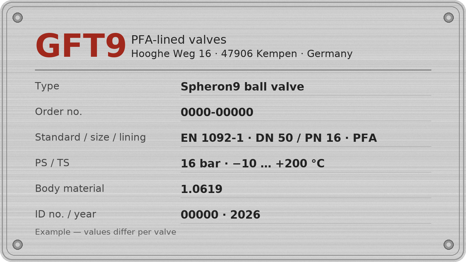
GFT9_Example_Nameplate

Type Plate
The stainless steel name plate is permanently riveted to the body. If the operator adds their own marking, they must make sure that the valve is suitable for the application concerned.

Body identification:
In accordance with DIN EN 19 and AD 2000 A4, the body is marked with:

  • Nominal size
  • Pressure rating
  • Body material
  • Manufacturer's mark
  • Melt number/Foundry identification
  • Foundry date

1.4 Weight DIN | ANSI

Weights are listed with the dimensions in Section 10. They are indicative; accurate weight on request.

1.5 Screws: Tightening Torque

Grease all screws and tighten them in diametrically opposite order!
The tightening torques stated for pipe screws and body screws must not be exceeded. An exception is described in Section 8, under 'Flange connection valve/pipe is leaking'. Recommended tightening torques are listed below.

1.5.1 Pipe Screws DIN | ANSI

DIN Pipe Screws
Size Screws Tightening Torque [Nm] — greased
DN 15 4 x M12 6
DN 20 4 x M12 8
DN 25 4 x M12 10
DN 40 4 x M16 20
DN 50 4 x M16 26
DN 80 8 x M16 25
DN 100 8 x M16 35
ANSI Pipe Screws
Size Screws Tightening Torque [in-lb / Nm] — greased
NPS ½" 4 x ½“ 45/5
NPS ¾" 4 x ½“ 55/6
NPS 1" 4 x ½“ 70/8
NPS 1½" 4 x ½“ 135/15
NPS 2" 4 x ⅝“ 220/15
NPS 3" 4 x ⅝“ 400/45
NPS 4" 8 x ⅝“ 310/35

1.5.2 Body screws DIN | ANSI

DIN Body Screws
Size Screws Tightening Torque [Nm / in-lb] — greased
DN 15 4 x M12 35/310
DN 20 4 x M12 35/310
DN 25 4 x M12 35/310
DN 40 4 x M16 45/398
DN 50 4 x M16 45/398
DN 80 8 x M16 50/442
DN 100 8 x M16 60/531
ANSI Body Screws
Size Screws Tightening Torque [in-lb / Nm] — greased
NPS ½" 4 x M12 310/35
NPS ¾" 4 x M12 310/35
NPS 1" 4 x M12 310/35
NPS 1½" 4 x M16 398/45
NPS 2" 4 x M16 398/45
NPS 3" 8 x M20 442/50
NPS 4" 12 x M24 531 /80

1.5.3 Cover screws DIN | ANSI

DIN Cover Screws
Size Screws Tightening Torque [Nm] [Nm/lbs] — greased
DN 15 4 x M10 30/266
DN 20 4 x M10 30/266
DN 25 4 x M12 50/442
DN 40 4 x M12 50/442
DN 50 4 x M12 50/442
DN 80 8 x M12 50/442
DN 100 8 x M12 50/442
ANSI Cover Screws
Size Screws Tightening Torque [Nm] [Nm/lbs] — greased
NPS ½" 4 x 3/8" 30/266
NPS ¾" 4 x 3/8" 30/266
NPS 1" 4 x ½“ 50/442
NPS 1½" 4 x ½“ 50/442
NPS 2" 4 x ½“ 50/442
NPS 3" 8 x ½“ 50/442
NPS 4" 8 x ½“ 50/442

1.5.4 Seat screws DIN | ANSI

DIN Seat Screws
Size Tightening Torque [Nm] [Nm/lbs] — greased
DN 15 3/26
DN 20 3/26
DN 25 6/53
DN 40 12/106
DN 50 16/142
DN 80 28/248
DN 100 30/265
ANSI Seat Screws
Size Tightening Torque [Nm] [Nm/lbs] — greased
NPS ½" 3/26
NPS ¾" 3/26
NPS 1" 6/53
NPS 1½" 12/106
NPS 2" 16/142
NPS 3" 28/248
NPS 4" 30/265

1.6 Flow Dynamics DIN | ANSI

1.6.1 KVS | CV Value

SizePlugSeat Ø (mm)Kvs (m³/h)Cv (US gpm)
DN 15 / NPS ½" V-plug 80.010.012
80.020.023
80.050.06
80.10.12
80.20.23
80.50.58
Parabolic plug 81.21.4
82.02.3
154.04.7
DN 20 / NPS ¾" V-plug 80.050.06
80.10.12
80.20.23
80.50.58
Parabolic plug 81.21.4
82.02.3
154.04.7
DN 25 / NPS 1" Parabolic plug 82.002.3
1544.7
2078.2
251112.8
DN 40 / NPS 1½" Parabolic plug 1544.7
2078.2
251112.8
301517.5
402832.6
DN 50 / NPS 2" Parabolic plug 1544.7
2078.2
251112.8
301517.5
402832.6
504248.9
DN 80 / NPS 3" Parabolic plug 301517.5
402832.6
504248.9
656575.7
80100117
U-plug 8090105
DN 100 / NPS 4" Parabolic plug 504248.9
656575.7
80100117
96155180
U-plug 8090105
96135157

Kvs in m³/h, Cv in US gpm (Cv ≈ 1.156 × Kvs). Values per seat diameter and plug; the same body serves DIN and ASME flanges.

1.6.2 Cavitation coefficient

SizeCavitation coefficient z for seat Ø (mm)
814152025304050658096
DN 15 / NPS ½"0.60.60.6––––––––
DN 20 / NPS ¾"0.60.60.6––––––––
DN 25 / NPS 1"0.60.60.6––––––––
DN 40 / NPS 1½"––0.60.60.550.5–––––
DN 50 / NPS 2"–––0.60.60.550.50.4–––
DN 80 / NPS 3"–––––0.550.50.450.320.3–
DN 100 / NPS 4"–––––––0.470.330.30.26
𝑋𝐹 = ∆𝑝 / 𝑝1−𝑝𝑣 Variable definition: XF = Differential pressure ratio p1 = Inlet pressure, absolute pv = Vapour pressure at operating temperature Δp = Differential pressure input/outlet Result interpretation: XF ≤ z : non-critical conditions XF ≤ 1,4 x z : tolerable cavitation XF > 1,4 x z : inadmissible cavitation

1.7 Actuation

The values specified in the tables apply to a seat/plug material of PTFE. With other materials, e.g. PTFE/carbon, higher closing forces are required. Please inquire at manufacturer's. If the maximum Δp is < p2, p2 is used in the tables. observe the application limits acc. to the pressure-temperature diagram in Section 1.8. A mechanical travel stop is required in the area marked. It is provided when: Δp > 10 bar / 145 psi to Seat-Ø 15-50 mm Δp > 6 bar / 87 psi to Seat-Ø ≥ 65 mm

Opening forces

DNNPSOpening force (N)
DN 15½"900
DN 251"900
DN 401½"2000
DN 502"2000
DN 803"800
DN 1004"800

Closing forces (N) by seat Ø and differential pressure Δp

Seat Ø (mm)Δp (bar)
12345678910111213141516
8290310330350370390410430450470495510525540555570
1433038543549054059564569575080086590093597010051040
1533038543549054059564569575080086590093597010051040
203904605255956657308008659351010114511951250130013551410
254505456407358309251020111512051305147515501625170517801855
30550680805935106511901320144515751705189019902095219522952400
4068088510851290149016951895209523002480275029153080325034153570
50830113014251720202023152610291032053500379040354280452547705020
651040150019602420289033503810427047405190567560706465686072557650
80130019702630330039604630530059606630730579458525910596851026510850
961600252034404370529062107130805089809900107901161012425132401406014880
12023753710502263797691902510371116721302914363156751682918084193172052721715
1453468541673329313112291317715142170411902320972228872457126404282042997131705

1.8 Pressure Temperature Diagram

Control Valve — pressure-temperature diagram

P-T diagram with vacuum range: heavy-duty bellows 16 bar −10 … 100 °C, linear to 6 bar at 200 °C · standard bellows 10 bar to 160 °C · −60 °C at 12 bar (AD 2000-Merkblatt W 10) · one diagram for 1.0619, 1.4408 and 1.4409 bodies · full vacuum (1 mbar abs) to 100 °C

2. Notes on safety

Read this manual before installing and commissioning the valve. It contains the essential instructions for installation, operation and maintenance.
Keep the manual where the valve is in use, so that staff can refer to it at any time.
For use in potentially explosive atmospheres, also follow Section 3.
Only qualified personnel may install, operate and service the valve.
The operator must define the staff's responsibilities and authority and how the staff are supervised.

Every warning and sign on the control valve itself must be followed and kept fully legible.
Disregarding these safety instructions can void all claims for damages.

It can also lead, for example, to the following hazards:

  • Loss of essential functions of the valve or plant.
  • Danger to persons from electrical, mechanical and chemical effects.
  • Harm to the environment from escaping hazardous substances.
Hazard_Sign_PFA_Lined_Valve_Manual

General hazard symbol!
Danger to persons.

Information_Sign_PFA_Lined_Valve_Manual

Safety symbol!
Disregarding this note can endanger the control valve and its function.

2.1 Intended use

GFT9 Imperium9 globe control valves are designed to pass and shut off fluids. They are pressure-containing components as defined by the Pressure Equipment Directive (PED).

The Imperium9 is designed for flow regulation and precise flow control in corrosive applications in chemical, pharmaceutical and other industries.

The valves are suitable for non-boiling liquids of group 1 in acc. with the Pressure Equipment Directive (PED). Solids in the medium can increase wear, damage the sealing faces or shorten the service life of the valve.

If the operating conditions are to differ from those the valve was ordered for, the operator must carefully check that design, materials and accessories still suit the new application (consult the manufacturer).

2.2 For the customer / operator

The operator is responsible for ensuring that:

  • hot or cold valve parts are guarded against accidental contact
  • the valve is correctly installed in the pipeline
  • flow velocities in continuous service stay within the normal limits for the line.
  • an appropriate collection system is used to contain drip leaks/leaks locally and harmlessly.

These points are not the manufacturer's responsibility.

The design does not take seismic loads into account.

Fire protection to DIN EN ISO 10497 cannot be provided, because the lining and other components are made of plastic.

2.3 Improper operation

Safe and reliable operation depends on using the valve only as described under Intended use (Section 2.1).

Hazard_Sign_PFA_Lined_Valve_Manual

The valve is delivered with flange caps fitted. They keep dirt off the plastic surfaces and protect them from mechanical damage. Remove them only immediately before installation.

3. Use in potentially explosive atmospheres

The valve has no electrical parts and no drive of its own (an actuator is an attachment). Its surface temperature is determined by the medium (and, on heated valves, by the heating medium). The valve carries no ATEX marking.

This manual does not give a general approval for use in potentially explosive atmospheres. Whether the valve may be used in such an area is decided for the specific application, in the operator's own assessment of the zone, the gas or dust group, the temperature class and the electrostatic behaviour of the medium.

GFT9 supports this assessment for a concrete application. On request we provide the design data needed for it — materials, lining type (standard or antistatic), earthing path, exposed non-conductive surfaces — and review the case with you. Contact: sales@gft9.shop.

Points the assessment must cover (from experience with lined valves; not a complete list):

  • Earthing of the valve, e.g. tooth lock washers under the pipe screws or an earthing cable (Section 6, Grounding).
  • Chargeable media (conductivity below 10⁻⁸ S/m): charge can build up on a standard lining; an antistatic lining (PFA/AS: surface resistance below 10⁹ Ω, leakage resistance below 10⁶ Ω) leads it away. With a standard lining the valve must stay completely filled or the atmosphere inside must be inerted; non-antistatic parts can limit the permitted zone and gas group.
  • Exposed non-conductive surfaces, e.g. lining at the flange faces or a sight-glass window.
  • Medium temperature and heating-medium temperature against the temperature class.
  • Actuators, positioners, limit switches, solenoid valves, sensors and heating jackets: their own explosion-protection conformity, per their manuals.
  • Abrasive media and dust deposits on the outside: inspection and cleaning intervals.
  • Plastic-lined valves must not be used with carbon disulfide.
  • Actuated control valve: continuous stem movement in modulating duty — to be covered in the assessment for the application.

WARNING — Ignition from improper use. Overheating, electrostatic charge or sparks can arise if the valve is used outside its intended use. → Use the valve only as described in this manual and as confirmed in the assessment for your application.

4. Safety note for TA Luft (Clean Air Act) versions

A TA Luft certificate is held for the Spheron9 ball valve. For other valves a TA Luft version is available on request. Any TA Luft certificate or manufacturer declaration is valid only if these operating instructions have been read and are followed.

  • Maintain the valve at regular intervals, check that the bolted connections are tight and retighten them where necessary.

5. Transport, storage and disposal

Handle the goods carefully in transit. Protect the valve from knocks and impacts while it is being transported.

Immediately on receipt, check that the consignment is complete and free of transport damage.

Take care not to damage the protective paint coat.

Hazard_Sign_PFA_Lined_Valve_Manual

Carry out all transport work in line with recognised good engineering practice and the accident prevention regulations.

Information_Sign_PFA_Lined_Valve_Manual

The valve is delivered with flange caps fitted. They keep dirt off the plastic surfaces and protect them from mechanical damage. Remove them only immediately before installation.

5.1 Storage

Valves that are not installed straight away must be stored correctly.
Store them in a dry, well-ventilated room free of vibration, at a temperature that is as constant as possible.
Keep elastomer parts out of UV light.
As a rule, the valves should not be stored for more than 10 years.

5.2 Return consignments

A safety information sheet / general safety certificate stating the field of application must always be enclosed with any return consignment.
Contact the Manufacturer for more Information in that regard.
The safety precautions and decontamination measures must be stated.

Hazard_Sign_PFA_Lined_Valve_Manual

Valves that have handled aggressive or toxic media must be rinsed and cleaned before they are returned to the manufacturer's works

5.3 Disposal

Parts of the valve may carry medium residues that are harmful to health and the environment; cleaning alone is therefore not enough.

Hazard_Sign_PFA_Lined_Valve_Manual

The medium can injure people and harm the environment!

Wear suitable personal protective equipment for all work on the valve.
Before disposing of the valve:

  • Collect any escaped medium or other substances and dispose of them according to local regulations.
  • Neutralise medium remaining in the valve.
  • Sort the valve materials by type (plastics, metals, etc.) and dispose of each according to local regulations.

6. Installation

  • Check the valve for transport damage on receipt. Do not install a damaged control valve.
  • Clean the valve and the adjoining pipework thoroughly before installation, removing all dirt and in particular hard particles.
  • Install the valve free of stress between aligned pipes, and tighten the bolts to the correct torque.
  • The gap between body and cover must be equal all the way round; this keeps the plug centred in the seat.
  • A bypass around the control valve allows the plant to keep running during maintenance work.
  • Depending on the Kv value, the flow area inside the valve can be considerably smaller than that of the nominal size. The pipe upstream of the valve must therefore be cleaned thoroughly to prevent blockages.
Hazard_Sign_PFA_Lined_Valve_Manual

Lock out remote-controlled actuators so that they cannot start unexpectedly.

6.1 Flange caps and gaskets

Leave the flange caps on until the valve is about to be installed.

If the plastic sealing faces are at particular risk of damage, for example from metal or enamelled mating flanges, PTFE-lined gaskets with metal inserts are recommended. Contact the Manufacturer for further discussion.

6.2 Direction of flow and installation position

The standard installation is in a horizontal pipe with the actuator vertical and on top. The valve may also be mounted vertically facing downwards, or at an angle. This is permitted only where the bellows cannot become contaminated.
An inclined actuator position is permitted only after consultation with the manufacturer. The actuator may then need a supporting structure.

6.3 Grounding

The valve must be grounded. The simplest way is to fit tooth lock washers under the pipe screws. Fit them under one pipe screw on each flange.

Upon customer request a set screw M6 is attached to each flange with a hex nut and washer as an additional earthing connection.

If this is not possible, grounding must be provided another way, e.g. with an earthing cable.

6.4 Test pressure

The test pressure PT must not be higher than 1.5 x PS(PN), with PS(PN) as stated in the valve marking.

6.5 Monitoring connection

The standard valve has no monitoring connection. Medium escaping past a damaged bellows is held by the PTFE back-up packing and shows at the packing nut (Section 7.2).
If a valve is supplied with a monitoring connection on the top cover (on request), connect it to a leak detector or a safe drain, or seal it with a plug suitable for the medium. Never leave it open.

7. Operation

7.1 Initial commissioning

The valves are normally leak-tested with air or water at the factory. Check the cover screws before commissioning. For tightening torques, see Section 1.5!

When the valve reaches operating pressure and temperature for the first time, retighten all bolted joints to prevent leaks. For tightening torques, see Section 1.5.

Hazard_Sign_PFA_Lined_Valve_Manual

Unless dry delivery was agreed, some water may remain in the flow passage of the valve. This water may react with the medium.

7.2 Improper operation and their consequences

  • Prevent the medium from crystallising, for example by heating. In extreme cases blocking or a leak may occur.
  • Solids in the medium increase wear.
  • Operating under cavitation increases wear.
  • Operating outside the pressure-temperature diagram can damage the valve.
  • The bellows seals the stem. The PTFE packing above it is only a back-up seal, set at the factory. A leak at the packing nut means the bellows has failed: take the valve out of service (Section 8) — do not try to stop the leak by tightening the packing nut.
  • Do not stand on, hang loads on or lift the valve by the actuator, the yoke or the positioner linkage; this can bend the stem or damage the bellows. If the actuator has a manual override (option), operate it by hand only, without an extension.

7.3 Shutdown

Comply with the local regulations when dismantling the valve!

As soon as the valve has been removed, fit flange caps to protect the flanges from mechanical damage. See also Section 6.1.
Lock out remote-controlled actuators so that they cannot start unexpectedly.

Hazard_Sign_PFA_Lined_Valve_Manual

Before undoing the flange connection, make sure that the plant has been depressurised and emptied!

Hazard_Sign_PFA_Lined_Valve_Manual

Clean the valve thoroughly before any repair. Medium can remain inside even after correct draining and flushing.

8. Malfunctions

Problem 1: Valve Does Not Close Fully (Internal Leakage)

Possible Causes:

  • Damaged seat sealing surface
  • Damaged cone sealing surface
  • Debris on seat or cone
  • Travel stop set incorrectly (valve not stroking fully)

Solution:

  1. Check travel stop setting (Section 9.2)
  2. If travel stop correct, remove top cover and inspect seat/cone
  3. Clean seat and cone with lint-free cloth
  4. If scratches visible on seat or cone: Replace seat cartridge
  5. Reassemble and retest

Problem 2: External Leak at Top Cover

Possible Causes:

  • Top cover bolts not torqued correctly
  • Gap < 1.0 mm (metal-on-metal contact)
  • Damaged sealing rings
  • Top cover or body flange surface damaged

Solution:

  1. Check top cover bolt torque: per Section 1.5.3 (cross pattern)
  2. Measure gap between top cover and body: Must be ≥ 1.0 mm
  3. If gap < 1.0 mm: Add gasket or contact manufacturer
  4. If gap correct and bolts torqued: Replace sealing rings (Section 9.6)
  5. Inspect flange surfaces for damage (may require rework)

Problem 3: External Leak at Valve Stem

Possible Causes:

  • Damaged bellows
  • Medium has passed the bellows and reached the PTFE back-up packing
  • Back-up packing worn after a bellows failure
  • Medium or pressure at a monitoring connection (if fitted, Section 6.5): the bellows is defective

Solution:

  1. Medium or pressure at the monitoring connection: depressurize, isolate and drain the valve (Section 7.3) and replace the bellows (Section 9.5)
  2. Do not try to stop a stem leak by tightening the packing nut: the leak shows that the bellows has failed
  3. If leak persists: Bellows is damaged - Replace bellows (Section 9.5)
  4. Fit new PTFE packing rings whenever the bellows is replaced
  5. Pressure test after bellows replacement

Problem 4: Valve Stem Binding / Rough Operation

Possible Causes:

  • Debris in top cover bore
  • Valve stem bent or damaged
  • Travel stop hitting top cover (no gap)
  • Bellows damage causing misalignment

Solution:

  1. Check travel stop gap (Section 9.2) - must have clearance
  2. Remove top cover and inspect valve stem (should be straight)
  3. Clean top cover bore and valve stem
  4. Check bellows for damage (replace if bent/kinked)
  5. Lubricate valve stem threads if dry

Problem 5: External Leak at Bottom Cover

Possible Causes:

  • Bottom cover not oriented correctly (inlet misaligned)
  • Bottom cover bolts loose or incorrect torque
  • Bottom cover gasket damaged
  • Bottom cover or body flange surface damaged

Solution:

  1. Verify bottom cover orientation: Inlet marking must align with body inlet
  2. Check bolt torque: per Section 1.5.3 (cross pattern)
  3. If leak persists: Remove bottom cover, inspect gasket and sealing surfaces
  4. Replace gasket or bottom cover if damaged
  5. Retorque bolts after reassembly

Problem 6: Actuator Does Not Move Valve

Possible Causes:

  • Coupling loose or disconnected
  • Actuator air pressure incorrect (pneumatic)
  • Actuator failure
  • Valve stem binding (see Problem 4)

Solution:

  1. Check coupling bolts are tight
  2. Verify air pressure to actuator (pneumatic): Per actuator TDS
  3. Only with the valve depressurized and isolated: de-energize the actuator, disconnect the coupling, then test actuator operation without the valve
  4. If actuator works but valve doesn't move: Check for valve binding
  5. Refer to actuator manual for actuator-specific troubleshooting

Problem 7: Flange connection valve/pipe is leaking

  1. Retighten the flange screws to the torque given in Section 1.5.1.
  2. If the joint still leaks, the screws may be tightened up to 10% above the recommended torque.
  3. If the leak persists, dismantle the valve and inspect it.

Problem 8: Noise, vibration or cavitation

  1. Operation during cavitation leads to increased wear (Section 7.2).
  2. Check the operating point against the sizing data and consult GFT9 with the process data.
  3. Inspect plug and seat for wear (Section 9.4).

Problem 9: Required flow not reached at full travel

  1. Compare the seat marking with the Kvs on the valve dataplate (Section 9.4, Step 6).
  2. Check the travel stop setting (Section 9.2).
  3. Check for debris on seat or cone (Problem 1).

Problem 10: Unstable control (hunting, overshoot)

  1. Check for stem binding (Problem 4).
  2. Check the positioner settings according to the positioner manual.

9. Maintenance

Before you start

  1. Make sure that the plant is depressurised and emptied before undoing any connection (Section 7).
  2. Lock out remote-controlled actuators so that they cannot start unexpectedly (Sections 7.3 and 9.3.1).
  3. Clean the valve thoroughly before starting any repair work. Medium can remain inside even after correct draining and flushing (Section 7). Wear suitable personal protective equipment for all work on the valve (Section 5.3).
  4. As soon as the valve is out of the line, fit flange caps to protect the flanges from mechanical damage (Section 6.1).

Tools Required

  • Torque wrench (5-60 Nm range)
  • Hex keys (metric set)
  • Seat-Screw-In-Tool (available from manufacturer)
  • Soft-face hammer
  • Pliers (for safety wire removal)
  • Cleaning materials (lint-free cloth, approved solvent)
  • Caliper or feeler gauge (gap measurement)

Recommended Spare Parts

  • Complete top cover assembly (pre-assembled with stem/bellows/cone)
  • Complete bottom cover assembly
  • Seat cartridge (Kvs-specific - order correct size)
  • Bellows assembly
  • Sealing ring kit (top cover seals)
  • Seat-Screw-In-Tool (DN 25, DN 40, DN 50, DN80, DN100)

Hazard_Sign_PFA_Lined_Valve_Manual
  • All maintenance work must be performed by qualified personnel
  • Use only original spare parts
    https://gft9.shop/pages/spare-parts-overview
  • Refer to valve identification data when ordering parts
  • Observe all safety requirements (Section 7.3 - depressurize, isolate, drain)

9.1 Regular Inspection Schedule

Daily / Before Operation:

  • Visual check for external leaks
  • Check actuator operation (if automated)
  • Verify no coating damage

Monthly:

  • Function test (manual or automated operation)
  • Travel stop position check
  • Check connection bolts (no loosening)

Semi-Annual:

  • Torque check on cover bolts (per Section 1.5.3 - cross pattern)
  • Actuator inspection (per actuator manual)
  • Coating condition inspection

Annual / After 10,000 Cycles:

  • Full valve inspection (may require disassembly)
  • Seat/cone inspection (replace if worn)
  • Bellows inspection (replace if damaged)
  • Sealing ring replacement (top cover)

9.2 Travel Stop Adjustment

When Required:

  • Valve does not close fully (internal leakage)
  • After actuator replacement or coupling adjustment
  • Annual inspection (verify correct setting)

Procedure:

Step 1: Close valve (actuator energized/de-energized per fail-safe mode)

Step 2: Loosen travel stop lock nut (counterclockwise)

Step 3: Verify gap between travel stop and top cover:

  • DN25-DN50: 0.5 mm minimum
  • DN80-DN100: 1.0 mm minimum

Step 4: If gap incorrect:

  • Adjust travel stop position (thread up/down on valve stem)
  • Recheck gap with feeler gauge

Step 5: Tighten lock nut (hold travel stop position while tightening)

Step 6: Test valve operation (5 full cycles)

  • PASS: Valve closes fully, no binding

9.3 Disassembly - Upper Section

When Required:

  • Seat/cone replacement (internal leakage)
  • Bellows replacement (external leak at stem)
  • Sealing ring replacement (leak at top cover)

IMPORTANT: Disassembly is the reverse of the assembly sequence in Section 9.8.

9.3.1 Actuator Removal (actuated valves)

Step 1: De-energize and lock out actuator (electrical/pneumatic)

Step 2: Disconnect air supply (pneumatic) or power (electric)

Step 3: Remove coupling bolts (record coupling position for reassembly)

Step 4: Remove actuator mounting screw

Step 5: Lift actuator off valve stem

9.3.2 Top Cover Removal

Step 1: Remove travel stop and lock nut (unthread from valve stem)

Step 2: Remove 4× M12 top cover bolts (cross-cross pattern - loosen gradually)

Step 3: Lift top cover vertically off body

NOTE: Valve stem, bellows, and cone remain attached to top cover

9.3.3 Bellows Assembly Removal from Top Cover

Step 1: Undo the packing nut (counterclockwise)

Step 2: Remove the thrust ring

Step 3: Remove sealing rings (note installation order for reassembly)

Step 4: Pull valve stem (with bellows/cone) out of top cover

9.3.4 Cone & Bellows Disassembly

Step 1: Clamp valve stem in soft-jaw vise (protect threads)

Step 2: Remove safety wire (round cord) from cone using pliers

Step 3: Unscrew cone from bellows (right-hand thread - counterclockwise)

Step 4: Unscrew bellows from valve stem (right-hand thread)

IMPORTANT: Do not damage sealing surfaces on cone or seat

9.4 Seat Replacement

When Required:

  • Internal leakage (seat test failure: >1 bubble/min)
  • Visible damage to seat sealing surface
  • Scratches or wear on seat

Special Tool Required: Seat installation/removal tool (order separately - see https://gft9.shop/pages/control-valve-spare-parts)

Procedure:

Step 1: Remove upper section (per Section 9.3)

Step 2: Insert seat removal tool into seat (engage internal hex or slots)

Step 3: Unscrew seat from body (right-hand thread - counterclockwise)

Step 4: Clean body seating area thoroughly (no debris or scratches)

Step 5: Inspect body sealing surface:

  • IF DAMAGED: Light rework possible (contact manufacturer for guidance)
  • IF SEVERELY DAMAGED: Body replacement may be required

Step 6: Install new seat:

  • Verify correct Kvs rating (check seat marking vs. valve dataplate)
  • Apply NO LUBRICANT to threads
  • Thread seat into body carefully (hand-start to avoid cross-threading)
  • Use seat installation tool
  • TORQUE MAX: DN 25: 6 Nm/ DN 40: 7Nm/ DN 50 :8 Nm/ DN 80: 12 Nm/ DN 100: 15 Nm - DO NOT EXCEED

Step 7: Reassemble upper section per the assembly sequence in Section 9.8

9.5 Bellows Replacement

When Required:

  • External leak at valve stem (bellows damage)
  • Visible cracks or damage to bellows convolutions
  • Contamination inside bellows (rare)

Procedure:

Step 1: Remove upper section and disassemble per Section 9.3

Step 2: Inspect old bellows for damage location (note for analysis)

Step 3: Install new bellows:

  • Thread onto valve stem (right-hand thread)
  • Tighten by hand until snug
  • Install cone onto bellows (NO LUBRICANT)
  • Install safety wire

Step 4: Reassemble per the assembly sequence in Section 9.8

Step 5: Pressure test after reassembly (verify no leaks)

9.6 Top Cover Sealing Rings Replacement

When Required:

  • External leak at top cover/body joint
  • Annual maintenance (preventive)

Procedure:

Step 1: Remove top cover per Section 9.3.2

Step 2: Remove old sealing rings from top cover grooves

Step 3: Clean grooves thoroughly (no debris)

Step 4: Install new sealing rings:

  • Install 2× plastic sealing rings (rotate 90° offset)
  • Insert pressure ring
  • VERIFY: Rings seat fully in grooves

Step 5: Reassemble top cover per Section 9.3.2 (reverse order)

Step 6: Torque top cover bolts: per Section 1.5.3 (cross pattern)

Step 7: VERIFY GAP: ≥1.0 mm between top cover and body

9.7 Bottom Cover Maintenance

When Required:

  • External leak at bottom cover/body joint
  • Bottom cover damage (impact, corrosion)

Procedure:

Step 1: Remove the valve from the line (Section 7.3) and rotate it for access to the bottom cover

Step 2: Remove 4× M12 nuts from stud bolts

Step 3: Remove bottom cover

Step 4: Inspect bottom cover sealing surface and gasket (replace if damaged, see Section 8, Problem 5)

Step 5: Install new or cleaned bottom cover:

  • VERIFY: Inlet orientation correct (flow direction matches body marking)
  • Install washers + nuts
  • TORQUE: per Section 1.5.3 (cross pattern)

Step 6: Pressure test (verify no leaks)

9.8 Reassembly Guidelines

Assembly sequence:

  1. Prior to assembly all parts are to be cleaned and the plastic-lined parts checked for damage.
  2. Check the seat and cone sealing surfaces: no scratches, dings or contamination (point 6 below). If rework is needed, contact the manufacturer (Section 9.4, Step 5).
  3. Install the seat with the seat installation tool: no lubricant on the threads, hand-start to avoid cross-threading, torque max. DN 25: 6 Nm / DN 40: 7 Nm / DN 50: 8 Nm / DN 80: 12 Nm / DN 100: 15 Nm — do not exceed (Section 9.4, Step 6).
  4. Bottom cover: verify the orientation — the inlet marking must align with the body inlet. Install washers and nuts and tighten crosswise per Section 1.5.3.
  5. Upper section: thread the bellows onto the valve stem (right-hand thread, hand-tight, no lubricant), screw the cone onto the bellows (no lubricant) and install the safety wire (Section 9.5, Step 3).
  6. Insert the valve stem with bellows and cone into the top cover. Install the PTFE packing rings (90° offset) and the thrust ring (Section 9.6, Step 4). Screw in the packing nut (greased thread).
  7. Place the top cover on the body and tighten the top cover bolts crosswise per Section 1.5.3.
  8. Measure the gap between top cover and body at 4 points: minimum 1.0 mm, even all round (point 4 below).
  9. Tighten the packing nut until the packing seals; the stem must still move freely.
  10. Fit the travel stop and lock nut and set them per Section 9.2.
  11. Mount the actuator. Never rotate the valve stem to fit the actuator coupling (point 5 below).
  12. Check the travel stop setting and the seat tightness (Sections 9.2 and 9.9).
  13. Pressure test (point 7 below), test pressure not above 1.5 × PS (Section 6.4): body test, then seat tightness test with the valve closed and pressurised on one side (≤ 1 bubble/min). Afterwards check the coating for damage.

CRITICAL POINTS:

1. Thread Direction:

  • All threads are RIGHT-HAND (clockwise to tighten)
  • DO NOT force - if resistance, check for cross-threading

2. Lubrication:

  • USE GREASE: Valve stem threads, packing nut thread
  • NO LUBRICANT: Seat threads, bellows threads, cone threads

3. Torque Values (Summary):

  • Seat: DN 25: 6 Nm/ DN 40: 7Nm/ DN 50 :8 Nm/ DN 80: 12 Nm/ DN 100: 15 Nm
  • Bottom cover bolts: per Section 1.5.3
  • Top cover bolts: per Section 1.5.3
  • Packing nut: Tighten until the packing seals; the stem must still move freely through its full travel.
  • Actuator mounting: [Per actuator manual]

4. Gap Verification:

  • ALWAYS measure gap between top cover and body after reassembly
  • MINIMUM: 1.0 mm
  • IF < 1.0 mm: Add gasket or contact manufacturer

5. Valve Stem Rotation:

  • NEVER rotate valve stem to fit actuator coupling
  • Stem MUST NOT be turned counterclockwise (will unthread from bellows)

6. Sealing Surface Protection:

  • Protect seat and cone sealing surfaces during all work
  • NO scratches, dings, or contamination allowed

7. Post-Reassembly Testing:

  • Always perform full pressure test after maintenance
  • Verify seat tightness (P12 test: ≤1 bubble/min)
  • Check actuator operation and travel stop setting

9.9 Field Calibration (Customer Site)

NOTE: Final calibration under water is recommended for best accuracy

Option 1: Return to Manufacturer

  • Ship valve + actuator assembly to manufacturer for calibration
  • Includes full pressure testing and a test report

Option 2: Field Calibration

  • Requires: Air supply, pressure gauges, water basin or large container or test bed

Calibration Procedure:

  1. Connect Inlet Flange to Air supply
  2. Submerge valve in water (minimum depth to cover entire body)
  3. Connect air supply to actuator
  4. Cycle valve 5× to ensure smooth operation
  5. Adjust travel stop until valve closes fully when submerged
  6. Verify closure: No bubbles from valve outlet when closed
  7. Perform seat tightness test (6 bar, check for bubbles: ≤1 bubble/min)
  8. Record calibration data (date, pressure, technician)

9.10 Maintenance Records

Recommended Documentation:

  • Date of maintenance
  • Work performed (travel stop adjustment, seat replacement, etc.)
  • Parts replaced (serial numbers if available)
  • Technician name
  • Test results (if applicable)
  • Next scheduled maintenance date

10. Dimensional Drawings

10.1 Dimensional Measurements DIN

Control Valve — dimensional drawing
Size L1 H3 Ød Øk ØD n × ØB Weight (indicative)
DN 15 130 mm 130 mm 45 mm 65 mm 95 mm 4 x 14 (M12) 6 kg
DN 20 150 mm 130 mm 58 mm 75 mm 105 mm 4 x 14 (M12) 6 kg
DN 25 160 mm 185 mm 68 mm 85 mm 115 mm 4 x 14 (M12) 11 kg
DN 40 200 mm 225 mm 88 mm 110 mm 150 mm 4 x 18 (M16) 16 kg
DN 50 230 mm 230 mm 102 mm 125 mm 165 mm 4 x 18 (M16) 19 kg
DN 80 310 mm 340 mm 138 mm 160 mm 200 mm 8 x 18 (M16) 39 kg
DN 100 350 mm 350 mm 158 mm 180 mm 220 mm 8 x 18 (M16) 44 kg

Indicative weights, in line with body volume. Accurate weight on request: sales@gft9.shop.

10.2 Dimensional Measurements ANSI

Control Valve — dimensional drawing
Size L1 H3 Ød Øk ØD n × ØB Weight (indicative)
NPS ½" 130 mm 130 mm 34.9 mm 60.3 mm 88.9 mm 4 x 15.9 6 kg
NPS ¾" 150 mm 130 mm 42.9 mm 69.8 mm 98.4 mm 4 x 15.9 6 kg
NPS 1" 160 mm 185 mm 50.8 mm 79.4 mm 108 mm 4 x 15.9 11 kg
NPS 1½" 200 mm 225 mm 73 mm 98.4 mm 127 mm 4 x 15.9 16 kg
NPS 2" 230 mm 230 mm 92.1 mm 120.7 mm 152.4 mm 4 x 19.1 19 kg
NPS 3" 310 mm 340 mm 127 mm 152.4 mm 190.5 mm 4 x 19.1 39 kg
NPS 4" 350 mm 350 mm 157.2 mm 190.5 mm 228.6 mm 8 x 19.1 44 kg

Indicative weights, in line with body volume. Accurate weight on request: sales@gft9.shop.

11. Sectional Drawing

Control Valve — sectional drawing with parts list positions
Pos. Item Material
1 Body, PFA-lined 1.0619 or 1.4408 / 1.4409 (A216 WCB, CF8M / CF3M)
2 Lining Virgin PFA or PFA/AS (antistatic)
3 Seat ring TFM-PTFE
4 Plug with stem TFM-PTFE; parabolic, V or U plug
5 Bellows seal PFA; standard or heavy-duty bellows
6 Cover As body material
7 Bonnet As body material
8 Stem packing and gasket PTFE
9 Packing nut Stainless steel
10 Travel stop Stainless steel
11 Bottom cover As body material
12 Cover bolting A2, A4 or 5.6 galvanised, per order
13 Bottom cover bolting A2, A4 or 5.6 galvanised, per order
14 Yoke nut Stainless steel
15 Stem connector, valve side Stainless steel
16 Stem connector, actuator side Stainless steel
17 Coupling clamp, 2 halves Stainless steel
18 Clamp screw A2, A4 or 5.6 galvanised, per order
19 Pneumatic actuator Spring-diaphragm; other actuators and positioners on request

12. Declaration of Conformity

The EU declaration of conformity for this product is supplied with every delivery and is available on request: sales@gft9.shop.

The product is designed and manufactured in accordance with the Pressure Equipment Directive 2014/68/EU.