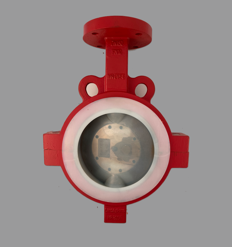
Installation and operating manual

PFA Lined Butterfly Valve

Papilon9 · transport, installation, operation and maintenance — read before you start.

Document
GFT9-PAP-UM-001
Revision
Rev. A · 2026-10-27
Language
English
Manufacturer
GFT9 · Kempen, Germany
PFA Lined Butterfly Valve

1 Technical Data

1.1 Manufacturer Information

GFT9
Hooghe Weg 16, 47906 Kempen, Germany
Email: sales@gft9.shop
Web: https://gft9.shop
Phone: +49 2152 9148591

1.2 Product Overview

Parameter Value
Name Papilon9
Operational characteristics On / Off; throttling with lever positions or actuator
Design norm DIN/ISO | ANSI
Size DN 40 – 600 | NPS 1½" – 24"
Flange dimensions EN 1092-1 PN 10 | ASME B16.5 Class 150; other drillings on request
Face to face dimensions ISO 5752 basic series 20 (EN 558-1 series 20)
Actuator EN ISO 5211 top flange F05 – F16 by size; stem double-D or square
Lining PFA, PFA/AS (antistatic) — PVDF, PP, UHMW-PE on request
Body 1.0619 (A216 WCB); 1.4408 (CF8M) or 1.4308 (CF8) on request
Pressure PN 10 — 10 bar DN 40 – 450 | 1½" – 18"; 6 bar DN 500 – 600 | 20" – 24" (see P-T diagram)
Temperature range −10 °C (1.0619) up to +200 °C — see P-T diagram
Custom Actuation, gearbox, lever with locking and adjustable positions
Quality Seat leakage test to DIN EN 12266-1 on every valve; EN 10204/3.1. 15 kV spark test on request
Certificates EU Pressure Equipment Directive 2014/68/EU

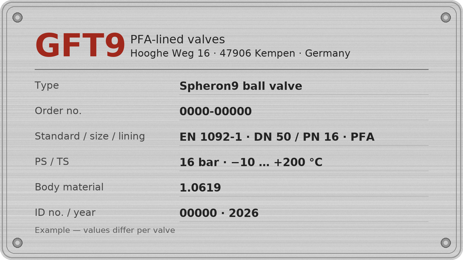
1.3 Type plate, conformity and body markings

GFT9_Example_Nameplate

Type Plate
The stainless steel name plate is permanently riveted to the body. If the operator adds their own marking, they must make sure that the valve is suitable for the application concerned.

Body identification:
In accordance with DIN EN 19 and AD 2000 A4, the body is marked with:

  • Nominal size
  • Pressure rating
  • Body material
  • Manufacturer's mark
  • Melt number/Foundry identification
  • Foundry date

1.4 Weight DIN | ANSI

No weight data available for DIN.
No weight data available for ANSI.

1.6 Flow Dynamics DIN | ANSI

1.6.1 KVS | CV Value

DIN Flow Rate
Size KVS Value
DN 40 136
DN 50 193
DN 65 266
DN 80 392
DN 100 585
DN 125 1015
DN 150 1495
DN 200 3050
DN 250 4510
DN 300 6500
DN 350 8760
DN 400 11350
DN 450 14400
DN 500 18000
DN 600 29200
ANSI Flow Rate
Size CV Value
NPS 1½" 136
NPS 2" 193
NPS 2½" 266
NPS 3" 392
NPS 4" 585
NPS 5" 1015
NPS 6" 1495
NPS 8" 3050
NPS 10" 4510
NPS 12" 6500
NPS 14" 8760
NPS 16" 11350
NPS 18" 14400
NPS 20" 18000
NPS 24" 29200

1.6.2 Cavitation coefficient

DIN Cavitation Coefficient
Size Cavitation Coefficient Z for Seat ø
DN 40 0.28
DN 50 0.32
DN 65 0.46
DN 80 0.63
DN 100 0.29
DN 125 0.40
DN 150 0.26
DN 200 0.23
DN 250 0.19
DN 300 0.16
DN 350 0.14
DN 400 0.12
DN 450 0.20
DN 500 0.19
DN 600 0.24
ANSI Cavitation Coefficient
Size Cavitation Coefficient Z for Seat ø
NPS 1½" 0.28
NPS 2" 0.32
NPS 2½" 0.46
NPS 3" 0.63
NPS 4" 0.29
NPS 5" 0.40
NPS 6" 0.26
NPS 8" 0.23
NPS 10" 0.19
NPS 12" 0.16
NPS 14" 0.14
NPS 16" 0.12
NPS 18" 0.20
NPS 20" 0.19
NPS 24" 0.24
𝑋𝐹 = ∆𝑝 / 𝑝1−𝑝𝑣 Variable definition: XF = Differential pressure ratio p1 = Inlet pressure, absolute pv = Vapour pressure at operating temperature Δp = Differential pressure input/outlet Result interpretation: XF ≤ z : non-critical conditions XF ≤ 1,4 x z : tolerable cavitation XF > 1,4 x z : inadmissible cavitation

1.7 Actuation

DIN Actuation Torque
Size Actuation Torque [Nm]
DN 40 18-90
DN 50 20-100
DN 65 35-61
DN 80 46-180
DN 100 63-360
DN 125 80-179
DN 150 128-725
DN 200 185-775
DN 250 287-1435
DN 300 410-1775
DN 350 550-3000
DN 400 650-3500
DN 450 600-1950
DN 500 650-2400
DN 600 890-3200
ANSI Actuation Torque
Size Actuation Torque [Nm]
NPS 1½" 18-90
NPS 2" 20-100
NPS 2½" 35-61
NPS 3" 46-180
NPS 4" 63-360
NPS 5" 80-179
NPS 6" 128-725
NPS 8" 185-775
NPS 10" 287-1435
NPS 12" 410-1775
NPS 14" 550-3000
NPS 16" 650-3500
NPS 18" 600-1950
NPS 20" 650-2400
NPS 24" 890-3200

1.8 Pressure Temperature Diagram

PFA Lined Butterfly Valve — — pressure-temperature diagram

P-T diagram with vacuum range: PN 10 — 10 bar −10 … 160 °C, linear to 6 bar at 200 °C · DN 500–600 / NPS 20–24: 6 bar · −60 °C at 7.5 bar (1.0619 body, AD 2000-Merkblatt W 10) · full vacuum (1 mbar abs) to 100 °C


2. Notes on safety

Read this manual before installing and commissioning the valve. It contains the essential instructions for installation, operation and maintenance.
Keep the manual where the valve is in use, so that staff can refer to it at any time.
For use in potentially explosive atmospheres, also follow Section 3.
Only trained, qualified personnel may install, operate and service the valve.
The operator decides who is responsible for each task and who supervises the work.

Follow every warning and marking on the valve itself, and keep them clean and readable.
Disregarding these safety instructions can void claims for damages
and can lead in particular to:

  • loss of essential functions of the valve or plant;
  • injury from electrical, mechanical or chemical hazards;
  • injury from the moving disc (crushing and shearing in the valve bore);
  • environmental harm from escaping hazardous media.
Hazard_Sign_PFA_Lined_Valve_Manual

General warning sign:
danger to persons.

Information_Sign_PFA_Lined_Valve_Manual

Safety sign:
ignoring this note can damage the valve or impair its function.

2.1 Intended use

The Papilon9 is pressure equipment under Directive 2014/68/EU (PED), designed to pass, shut off and throttle fluids in pipelines.

The Papilon9 is a quarter-turn butterfly valve with PFA-lined body and disc, in wafer design (clamped between two pipe flanges) or lug design (body with tapped holes). It is installed between flanges to EN 1092-1 PN 10 or ASME B16.5 Class 150; the face-to-face length conforms to ISO 5752 basic series 20. It is used for on/off duty and, with the lever positions or an actuator, for throttling (see Section 7.4). For the installation position, see Section 6.2.

Operating limits, see the type plate and the pressure-temperature diagram in Section 1.8:

  • PN 10: 10 bar up to +160 °C, then falling linearly to 6 bar at +200 °C.
  • DN 500 – 600 / NPS 20" – 24": 6 bar over the whole temperature range.
  • Below −10 °C (body 1.0619): 7.5 bar down to −60 °C (DN 500 – 600: 4.5 bar).
  • Vacuum: 1 mbar abs up to +100 °C, rising to 100 mbar abs at +200 °C.

The valves are designed for gases, vapours and liquids of fluid group 1 as defined in Article 13 of Directive 2014/68/EU. The wetted parts are the lining (Pos. 3) and the disc (Pos. 2), in PFA or PFA/AS (antistatic); metal discs are available on request. Lining and disc must be resistant to the medium. Media that carry solids wear the lining and disc faster, can damage the sealing faces and shorten the service life.

When the valve opens, the disc swings out of the body into the adjoining pipe on both sides. The valve may only be used where the mating flanges and pipes leave enough room for the disc (Section 6.3).

Use at the end of a line (one side without a mating pipe, dead-end service) is only permitted after consultation with the manufacturer.

If the operating conditions are to differ from those the valve was ordered for, the operator must check that design, materials and accessories still suit the new duty. Consult GFT9 before making the change.

2.2 For the customer / operator

The operator is responsible for ensuring that:

  • hot or cold surfaces are guarded against accidental contact
  • the valve is correctly installed in the pipeline
  • flow velocities in continuous service stay within the normal limits for the line
  • any drips or leaks are caught locally and safely
  • gearboxes and actuators fitted later are matched to the valve (top flange, stem end and torque, see Sections 1.7 and 6.6)
  • nobody can reach into the valve bore while the valve can be operated — the closing disc can crush fingers and tools.

These points lie outside the manufacturer's scope.

The design does not take seismic loads into account.

Because the lining and seals are plastic, the valve is not fire-safe to DIN EN ISO 10497.

2.3 Improper operation

Safe and reliable operation depends on using the valve only as described under Intended use (Section 2.1).

Never run the valve outside the limits on the type plate and in the P-T diagram (Section 1.8), not even briefly.

Hazard_Sign_PFA_Lined_Valve_Manual

The factory-fitted flange caps keep dirt off the PFA faces and protect them from knocks; take them off only when the valve is about to go in. Valves are delivered with the disc slightly open (lever in the first notch after "closed", or a few degrees open with gearbox or actuator), so that the disc edge stays inside the body. Leave it in this position until the valve is installed (Section 6.4).

3. Safety notes for use in potentially explosive atmospheres (Directive 2014/34/EU, ATEX)

Because the valves are designed for use in potentially explosive atmospheres, they fall under the conformity assessment procedure of Directive 2014/34/EU (ATEX).

Within this assessment, the valves were analysed for ignition hazards to EN 13463-1 against the essential health and safety requirements. The result:

  • The valves have no ignition source of their own. They may be operated manually, mechanically or electrically.
  • The valves fall outside the scope of the ATEX directive, so no ATEX marking is required.
  • Use in potentially explosive atmospheres is permitted.

Supplementary notes:

  • Electric and mechanical actuators require a separate ATEX conformity assessment of their own.

Where the valves are used in potentially explosive atmospheres, each requirement of the intended use must be strictly followed.

3.1 Intended use

Even brief improper operation can seriously damage the valve. With regard to explosion protection, improper operation can create ignition sources such as overheating, electrostatic or induced charges, and sparks of mechanical or electrical origin. Only strict adherence to the intended use prevents them. See also Directive 95/C332/06 (ATEX 118a), which sets minimum requirements for the health and safety protection of workers potentially at risk from explosive atmospheres.
For chargeable liquids (conductivity < 10⁻⁸ S/m), two cases must be distinguished:

3.1.1 Chargeable liquid and standard (non-antistatic) lining

Charges can occur on the lining surface, which may produce discharges inside and outside the valve.

  1. Discharges inside the valve:
    While the valve is completely filled with medium, these discharges cannot cause ignition. When the valve is only partly filled, for example during emptying and filling, an explosive atmosphere must be prevented from forming, e.g. by nitrogen blanketing. A waiting time of one hour is recommended before the valve is removed from the plant, so that static peak charges can dissipate. To safely prevent ignitions, the valve must always be completely filled with medium, or an inert gas layer must be used to exclude a potentially explosive atmosphere.
  2. Discharges outside the valve:
    Where the standard (non-antistatic) lining extends outwards at the sealing faces or is exposed to the surrounding atmosphere, charges can discharge to adjacent valves or attachments. To rule out explosion hazards and accidents, the atmosphere around the valve must not be explosive.

3.1.2 Chargeable liquid and antistatic lining

No hazardous charges can occur because charges are discharged directly via the lining and shell (surface resistance < 10⁹ Ohm, leakage resistance < 10⁶ Ohm). Components fitted in non-antistatic versions can, however, limit the permitted ATEX zone and explosion subgroup, even with an antistatic lining. In such cases, it is necessary to consult the manufacturer. TRGS 727 (“Technical Rules for Hazardous Substances: Avoidance of Ignition Hazards Due to Electrostatic Charges”) states that static discharges from non-antistatic linings arise only in combination with a non-conductive medium; they therefore fall within the plant operator's responsibility. Such static discharges are not an ignition source originating in the valve itself.
Additional safety measures include:

  • The medium temperature must not be higher than the limit of the applicable temperature class, nor higher than the maximum permissible medium temperature stated in this operating manual.
  • For heated valves (e.g. with a heating jacket), comply with the temperature classes specified in the Annex.
  • To ensure safe and reliable operation, regular inspections must verify that the valve is properly maintained and kept in technically perfect condition.
  • Liquids containing abrasive constituents increase wear on the valve, so shorter inspection intervals than usual are needed.
  • Actuators and electrical peripheral devices (for example temperature, pressure and flow sensors) must meet the applicable safety and explosion protection requirements.
  • The valve must be grounded, e.g. by placing tooth lock washers under the pipe screws. If this is not possible, grounding must be provided another way, e.g. with an earthing cable.
  • Add-on devices such as actuators, positioners and limit switches must meet the relevant explosion protection safety regulations and, where required, be built to ATEX.
  • Pay particular attention to the safety and explosion protection instructions in the operating manuals of these devices.
  • Plastic-lined valves must not be used for carbon disulfide.

4. Safety note for TA Luft (Clean Air Act) versions

A TA Luft certificate is held for the Spheron9 ball valve. For other valves a TA Luft version is available on request. Any TA Luft certificate or manufacturer declaration is valid only if these operating instructions have been read and are followed.

  • Maintain the valve at regular intervals, check that the bolted connections are tight and retighten them where necessary.

5. Transport, storage and disposal

Handle the goods carefully in transit. Protect the valve from knocks and impacts while it is being transported.

Immediately on receipt, check that the consignment is complete and free of transport damage.

Take care not to damage the protective paint coat.

Hazard_Sign_PFA_Lined_Valve_Manual

Carry out all transport work in line with recognised good engineering practice and the accident prevention regulations.

Information_Sign_PFA_Lined_Valve_Manual

The valve is delivered with flange caps fitted. They keep dirt off the plastic surfaces and protect them from mechanical damage. Remove them only immediately before installation.

5.1 Storage

Valves that are not installed straight away must be stored correctly.
Store them in a dry, well-ventilated room free of vibration, at a temperature that is as constant as possible.
Keep elastomer parts out of UV light.
As a rule, the valves should not be stored for more than 10 years.

5.2 Return consignments

A safety information sheet / general safety certificate stating the field of application must always be enclosed with any return consignment.
Contact the Manufacturer for more Information in that regard.
The safety precautions and decontamination measures must be stated.

Hazard_Sign_PFA_Lined_Valve_Manual

Valves that have handled aggressive or toxic media must be rinsed and cleaned before they are returned to the manufacturer's works

5.3 Disposal

Parts of the valve may carry medium residues that are harmful to health and the environment; cleaning alone is therefore not enough.

Hazard_Sign_PFA_Lined_Valve_Manual

The medium can injure people and harm the environment!

Wear suitable personal protective equipment for all work on the valve.
Before disposing of the valve:

  • Collect any escaped medium or other substances and dispose of them according to local regulations.
  • Neutralise medium remaining in the valve.
  • Sort the valve materials by type (plastics, metals, etc.) and dispose of each according to local regulations.

6. Installation

Check the valve for transport damage on receipt. Do not install a damaged valve.

  • Clean the valve and the adjoining pipework thoroughly before installation, removing in particular hard particles such as weld spatter, scale or blasting grit.
  • The mating flange faces must be flat and clean. Remove burrs, weld beads, old paint and corrosion before installing the valve.
  • Install the valve free of stress between aligned pipes, and tighten the bolts to the correct torque. The valve must not be used to pull misaligned or non-parallel flanges together.
  • Lift heavy valves (weights, see Section 1.4) with slings around the body. Never lift the valve by the lever, gearbox, actuator or disc, and never pass slings through the valve bore.
  • Keep the disc in its delivery position, slightly open, until the valve is installed (Section 6.4).
  • Valves with a spring-return actuator are delivered with the actuator separate; mount it after installation (Section 6.6).
  • The lever, gearbox or actuator must have room to move through the full stroke of 90°.
Hazard_Sign_PFA_Lined_Valve_Manual

Lock out remote-controlled actuators so that they cannot start unexpectedly.
Never reach into the valve bore: the disc can close at any time and crush fingers or tools.

6.1 Flange caps and gaskets

Leave the flange caps on until the valve is about to go in (Section 2.3).

The lining (Pos. 3) forms the sealing faces to the mating flanges. Additional gaskets are not required. Do not apply sealing compound, grease or adhesive to the lining faces.

If the PFA faces are at particular risk, for example against metal or enamel flanges, or against flanges that are not flat, a PTFE envelope gasket with a metal core may be fitted between valve and flange. A gasket lengthens the bolted joint: check bolt length and disc clearance (Section 6.3) and consult GFT9.

6.2 Direction of flow and installation position

The valve seals in both directions and can be installed regardless of the direction of flow. It may be mounted in horizontal or vertical lines in any orientation.

With solids-laden media, mount the valve in a horizontal line with the stem lying horizontal. Orient it so that the bottom half of the disc swings downstream when the valve opens; this keeps sediment away from the lower stem bearing.

Disturbed flow increases the operating torque and the wear of disc and seat. Where possible, do not install the valve directly downstream of bends, pumps, reducers or control valves.

6.3 Pipe bore and disc clearance

When the valve opens, the disc swings out of the body on both sides and projects into the mating flanges and pipes. The inner diameter of the mating flanges and pipes must leave enough room for the disc over its whole swing. The minimum inner diameter for each size is available from the manufacturer on request.

  • Check the clearance in particular with lined or plastic pipes and flanges (the lining reduces the bore), with thick-walled flanges, reducers and stub ends.
  • Do not install the valve directly against another valve or fitting whose moving parts swing into the same space, e.g. the disc of a wafer check valve.
  • If the bore is too small, a lined spacer ring between flange and valve can provide the clearance. Contact the manufacturer.

A disc that strikes the pipe damages its lining, and the valve no longer closes tightly.

6.4 Installing the valve between the flanges

Step 1:
Set the disc slightly open: with lever, engage the lever in the first position after "closed"; with gearbox or actuator, move the disc a few degrees out of the closed position. The disc edge must stay inside the body. Do not install the valve with the disc fully closed — clamping the lining while the disc sits in the seat deforms the seat — and not open, where the projecting disc can be damaged.

Step 2:
Spread the mating flanges only as far as necessary to insert the valve. Do not drag the lining faces over flange edges or bolt threads.

Step 3:
Wafer body: insert the lower flange bolts first so that they carry the valve, set the valve between the flanges and insert the remaining bolts. Centre the body on the flange bolts so that the lining is concentric with the pipe bore (centring holes, see Section 10). Lug body: screw the bolts into the tapped holes from both sides; the bolts must not bottom in the tapped holes. Lug positions and threads per size: dimension sheet GFT9-PAP-DIM-002 (Downloads).

Step 4:
Fit all flange bolts and nuts and bring them to finger tightness, working crosswise.

Step 5:
Open the disc slowly to the fully open position and close it again. The disc must not touch the pipe or the flanges at any point (Section 6.3). If it does, re-centre the valve.

Step 6:
Set the disc slightly open again and tighten the flange bolts crosswise, in diametrically opposite sequence, in several passes to the final torque. Recommended tightening torques for the gasket-free PFA flange faces are available from the manufacturer on request. Do not exceed them: over-tightened bolts squeeze the PFA faces and increase the operating torque.

Step 7:
Operate the valve through a full stroke open – closed and check that it moves smoothly.

Note: Take the valve out before any welding or flame-cutting on the adjoining pipework. Heat conducted into the body ruins the PFA lining.

6.5 Grounding

The valve must be grounded. The simplest method is a toothed lock washer under one flange bolt on each side, biting through the coating to connect body and flange.

Where that is not possible, connect body and pipe with an earthing cable.

With PFA/AS (antistatic) lining, electrostatic charge is led off through the lining into the body, so the body must always be grounded. In potentially explosive atmospheres, also follow Section 3.

6.6 Lever, gearbox and actuator

The top flange conforms to EN ISO 5211; the flange size for each valve size (F05 – F16) is listed in Section 10. The stem end is double-D or square. The lever locks in adjustable positions.

  • Select gearbox or actuator for the actuating torque of the valve (Section 1.7) with a safety margin; viscous, crystallising or solids-laden media need a larger margin. Consult the manufacturer when selecting.
  • Coupling and bracket must match the top flange and stem end of the valve and the flange of the actuator.
  • Mount the actuator with disc and actuator in the same position (both closed).
  • Set the end stops of gearbox or actuator so that the disc stops exactly in the closed position and at 90° open. Travel beyond the closed position presses the disc into the lining and damages the seat.
  • Spring-return actuators are delivered separately; mount them only after the valve has been installed, so that the spring does not hold the disc in the seat during storage.
  • Observe the operating manual of the gearbox or actuator.

Mounting step by step: see Section 9.6.

6.7 Test pressure

The test pressure PT must not be higher than 1.5 x PS(PN), with PS(PN) as stated in the valve marking.

If the line is pressure-tested with the valve closed, the pressure across the disc must not exceed the rated pressure PS on the type plate, unless GFT9 confirms a higher value.

Clean and flush the pipe only with agents that do not attack the lining. Do not pass pigs or cleaning devices through the valve.

7. Operation

7.1 Initial commissioning

Every valve is pressure-tested before shipment, with a seat leakage test to DIN EN 12266-1. Check the flange bolts and the body screws before commissioning.

Flush the pipe with the valve fully open before commissioning to remove foreign matter. Hard particles trapped between disc and seat damage the lining.

After long storage the seat may have deformed slightly where the disc rests, and the first strokes need a higher torque. Operate the valve slowly through several full strokes before filling the line (see also Section 9.7).

When the valve reaches operating pressure and temperature for the first time, retighten all bolted joints to prevent leaks. Tighten crosswise, in diametrically opposite sequence; recommended tightening torques are available from the manufacturer on request.

Hazard_Sign_PFA_Lined_Valve_Manual

Unless dry delivery was agreed, some water from the factory test may remain in the valve. Check whether it can react with the process medium.

7.2 Operating errors to avoid

  • Keep lever, gearbox or actuator fitted whenever the line is in service; a free disc is swung by the flow.
  • Move the lever slowly, especially when closing; a sudden stop of the flow causes pressure surges.
  • Avoid throttling for long periods just off the closed position. The high flow velocity in the narrow gap causes cavitation and wear of disc and seat.
  • Prevent the medium from crystallising, for example with trace heating. Crystals between disc and seat damage the lining; in extreme cases the disc blocks.
  • Solids in the medium increase wear.
  • Media that make the lining swell can cause the disc to jam. Check the chemical resistance of lining and disc.
  • Liquid enclosed between two closed valves expands when heated. Provide pressure relief in such pipe sections.
  • If the disc blocks, do not apply force — the stem may break if the admissible torque (Section 1.7) is exceeded.
  • Cavitation erodes disc and lining; avoid conditions that cause it.
  • Operating outside the P-T diagram damages the valve.
  • Do not transport the valve using the lever, gearbox or actuator.
  • Never lengthen the lever with a pipe or bar; the extra force can break the stem.

7.3 Shutdown

Comply with the local regulations when dismantling the valve!

Before removing the valve, set the disc slightly open (Section 6.4). As soon as the valve is out of the line, refit the flange caps to protect the PFA faces (Section 6.1).
Lock out remote-controlled actuators so that they cannot start unexpectedly.

Hazard_Sign_PFA_Lined_Valve_Manual

Before undoing the flange connection, make sure that the plant has been depressurised and emptied!

Hazard_Sign_PFA_Lined_Valve_Manual

Clean the valve thoroughly before any repair. Medium can remain inside even after correct draining and flushing.

7.4 Operating positions and throttling

The valve opens and closes by a quarter turn (90°).

  • Lever parallel to the pipe axis: valve open. Lever at right angles to the pipe axis: valve closed.
  • With gearbox or actuator, the position indicator shows the disc position.
  • The lever locks in its adjustable positions. For throttling, lock it in the required position.
  • For throttling, choose an opening angle that keeps the disc away from the closed position (Section 7.2). For control duty, use an actuator with positioner.
  • The Kv value of the fully open valve is given for each size in Section 1.6.

8. Malfunctions

Leak at the flange joint between valve and pipe:

  1. Retighten the flange bolts crosswise, in diametrically opposite sequence. Recommended tightening torques are available from the manufacturer on request. If the joint still leaks, the bolts may be taken up to 10 % above the recommended torque.
  2. Check that the valve is centred and that the flanges are parallel and aligned: the lining face (Pos. 3) must cover the sealing face of the mating flange all round (Section 6.4).
  3. Still leaking? Take the valve out of the line (Section 9.2) and examine the PFA faces and the mating flange faces for scratches, imprints, deposits and cold flow. A damaged lining is replaced together with the disc (Section 9.4).

Medium escapes at the body joint, at the top flange or at the bottom of the body:

  1. Take the valve out of service, depressurise and drain the line. Medium outside the lining attacks the metal body (Pos. 1) and the backing support rings (Pos. 4).
  2. The stem seals are self-adjusting and cannot be tightened from outside. Remove the valve (Section 9.2), replace the stem seals (Pos. 5) and inspect lining and disc shaft (Pos. 2) at the stem passage (Sections 9.3 and 9.4).

Valve passes in the closed position:

  1. Is the disc fully closed? Check the lever position or the position indicator; with gearbox or actuator, check the closed end stop (Section 6.6).
  2. Is there foreign matter or deposit between disc and seat? Open the valve fully, flush, and close it again.
  3. Is the pressure within the operating limits (Section 2.1 and Section 1.8)?
  4. If the valve still passes, the seat of the lining (Pos. 3) or the disc edge (Pos. 2) is worn or damaged, or the backing support rings (Pos. 4) have lost their preload: dismantle and inspect the valve (Sections 9.3 and 9.4).

Disc does not open or close fully:

  1. Is there foreign matter, deposit or crystallised medium in the bore? Flush the valve, or heat it to dissolve deposits if the process allows (Section 7.2).
  2. Does the disc touch the pipe, the flange or an adjoining fitting? See "Disc touches the pipe or flange".
  3. Gearbox or actuator: are the end stops set correctly, is the coupling seated on the stem and not worn, is the actuator torque sufficient (Section 1.7)? The operating manuals of the gearbox and actuator manufacturers contain the instructions for setting the end stops.
  4. Is the stem or the coupling deformed? Do not apply force.
  5. Has the lining swollen in contact with the medium? Consult the manufacturer about a suitable lining material.

Operating torque higher than stated in Section 1.7:

  1. Never apply force to the lever or use an extension; the stem may break if the admissible torque is exceeded (Section 7.2).
  2. After storage or a long standstill, operate the valve slowly through several full strokes; the lining recovers its shape and the torque falls (Section 9.7).
  3. Crystallised or solidified medium in the valve: keep the medium from crystallising, for example with trace heating (Section 7.2), and flush the valve.
  4. Over-tightened flange bolts press the lining into the bore. Loosen the bolts and retighten them crosswise to the recommended torque (Section 6.4).
  5. Pipe forces or misaligned flanges distort the body. Support the pipe and align the flanges.
  6. Disturbed flow directly downstream of bends or pumps increases the torque (Section 6.2).
  7. If the torque is still too high, dismantle the valve and inspect the lining (Pos. 3), the backing support rings (Pos. 4) and the stem seals (Pos. 5), see Sections 9.3 and 9.4.

Disc touches the pipe or flange (scraping noise, disc stops before fully open):

  1. Stop operating the valve and close it.
  2. Check the inner diameter of the mating flanges, pipes and any adjoining fitting against the swing of the disc (Section 6.3).
  3. Check that the valve is centred on the flange bolts; if necessary loosen the bolts, re-centre the valve and retighten (Section 6.4).
  4. Inspect the lining of the disc (Pos. 2). If it is damaged, replace lining and disc as a unit (Section 9.4).

Actuated valve does not operate:

  1. Check the power or air supply to the actuator.
  2. Check that the pilot or solenoid valve is correctly wired and piped.
  3. Is the coupling seated on the stem and is the bracket firmly bolted (Section 9.6)?
  4. Check for foreign objects trapped in the valve.
  5. Manual valve: see "Operating torque higher than stated in Section 1.7".

Disc vibrates or the valve is noisy in an intermediate position:

  1. Is the valve throttling close to the closed position? Choose a larger opening angle, or consult the manufacturer about the valve size (Section 7.4).
  2. Is the lever locked in its position, and is the gearbox or actuator free of play?
  3. A noise like gravel in the line indicates cavitation. Reduce the pressure difference across the valve (Section 7.2).

Lining is damaged (cracks, blisters, deformed flange faces):

  1. Take the valve out of service. Through a damaged lining the medium reaches the metal body.
  2. Typical causes: operation outside the pressure-temperature diagram or the vacuum limits (Section 1.8), abrasive solids, a disc striking the pipe, over-tightened flange bolts, welding near the valve, an unsuitable medium.
  3. Replace lining and disc as a unit, or return the valve to GFT9 (Section 9.4), and remove the cause before returning the valve to service.

In General: Never apply force to the lever or use an extension. Depressurise and drain the line before undoing any connection.

9. Maintenance

Before you start

  1. Make sure that the plant is depressurised and emptied before undoing any connection (Section 7).
  2. Lock out remote-controlled actuators so that they cannot start unexpectedly (Section 7.3).
  3. Clean the valve thoroughly before any repair. Medium can remain inside even after correct draining and flushing (Section 7). Wear suitable personal protective equipment for all work on the valve (Section 5.3).
  4. As soon as the valve is out of the line, refit the flange caps to protect the PFA faces (Section 6.1).
  • Repairs may only be carried out by qualified staff with suitable tools.
  • Part names and item numbers (Pos. 1 – 5) are shown in the sectional drawing, Section 11.
  • Body screws, lever, gearbox, coupling and bracket used in the steps below are not shown in the parts list; order them from GFT9 with the valve identification.
  • When ordering spare parts, quote all data from the type plate.
  • Use genuine GFT9 spare parts only.
  • Wear parts are the lining (Pos. 3) with the disc and shaft (Pos. 2) as one pre-assembled unit, the backing support rings (Pos. 4) and the stem seals (Pos. 5). Replace the stem seals whenever the body has been opened.
  • Check the bolted joints regularly, at intervals suited to the duty, and retighten them if needed. Recommended tightening torques are available from the manufacturer on request.

Hazard_Sign_PFA_Lined_Valve_Manual

Make sure that when working on the butterfly valve it is drained. See also Section 7.3

9.1 Routine checks

Check the valve at intervals that suit the operating conditions (medium, temperature, number of strokes). Abrasive or crystallising media need shorter intervals.

  • Visual check for leaks at the flanges, at the body joint, at the top flange and at the bottom of the body (Section 8).
  • Check that flange bolts and body screws are tight.
  • Where the process allows, operate valves that stay in one position for a long time through a full stroke at intervals, so that the disc does not stick in the seat.
  • Gearbox or actuator: check the end stops, the coupling and the fastening of the bracket.
  • Check the grounding connection (Section 6.5).

9.2 Removing the valve from the line

Step 1:
Depressurise, drain and flush the plant (Section 7.3). Lock out remote-controlled actuators so that they cannot start unexpectedly.

Step 2:
Set the disc slightly open so that it stays inside the body.

Step 3:
Support the valve (weights, see Section 1.4). Undo and remove the flange bolts; with lug bodies, undo the bolts on both sides.

Step 4:
Spread the mating flanges slightly and lift the valve out without dragging the lining faces over the flange edges.

Step 5:
Fit the flange caps immediately (Section 6.1).

9.3 Dismantling

9.3.1 Lever, gearbox or actuator

Step 1:
Close the disc and mark how lever, gearbox or actuator sits on the body.

Step 2:
Remove the lever, or the gearbox or actuator together with coupling and bracket.

9.3.2 Body

Step 1:
Put a match mark across the joint of the two body halves (Pos. 1) so that each half goes back in the same place.

Step 2:
Lay the valve on a clean, soft surface with the disc closed.

Step 3:
Loosen the body screws a little at a time, one after the other. The joint is under preload from the backing support rings (Pos. 4) and opens slightly as the screws come free.

Step 4:
Lift off one body half and take out lining (Pos. 3) and disc (Pos. 2) together, without separating them. Do not pull the disc shaft out of the lining — the lining at the stem passage is easily damaged.

9.3.3 Stem seals and backing support rings

Step 1:
Remove the stem seals (Pos. 5) from the neck pockets of the body.

Step 2:
Remove the backing support rings (Pos. 4) from the body halves.

Step 3:
Clean all parts. Do not use metal scrapers or wire brushes on PFA surfaces.

9.4 Inspection and replacement of wear parts

  • Lining (Pos. 3): sealing faces, seat and stem passage must be free of scratches, cuts, imprints, cracks and blisters.
  • Disc with shaft (Pos. 2): the lining of disc and shaft and the disc edge must be undamaged, the shaft straight and the stem end not worn.
  • Backing support rings (Pos. 4): replace them if they are hardened, cracked, swollen or permanently deformed.
  • Stem seals (Pos. 5): always replace.
  • Body halves (Pos. 1): corrosion on the inside of the body shows that medium has passed the lining. Inspect the lining with particular care and consult the manufacturer.

If lining or disc is damaged, replace both: lining and disc are supplied as a pre-assembled spare unit (disc with shaft fitted in the lining) together with new stem seals and backing support rings. Do not separate disc and lining. Alternatively, return the valve to GFT9 for overhaul. Quote the type plate data when ordering. GFT9 can check linings with a spark test on request.

9.5 Assembly

Prior to assembly all parts are to be cleaned and the plastic-lined parts checked for damage.

Step 1:
Insert the backing support rings (Pos. 4) into the body halves (Pos. 1). They must lie evenly and must not be twisted.

Step 2:
Insert the stem seals (Pos. 5) into the neck pockets.

Step 3:
Place the pre-assembled unit of lining (Pos. 3) and disc (Pos. 2), disc closed, into the first body half, with the shaft passing through the stem seal.

Step 4:
Place the second body half according to the marks.

Step 5:
Insert the body screws and tighten them alternately until the body halves are close together but not yet in contact. Open and close the disc a few times so that lining and disc align.

Step 6:
With the disc closed, tighten the body screws alternately until the body halves are in full contact. Tightening torques for the body screws are available from the manufacturer on request.

Step 7:
Operate the valve through several full strokes. It must move smoothly and without jerks.

Step 8:
Before the valve is returned to service, a shell and seat tightness test to DIN EN 12266-1 is recommended. The test pressure must not exceed 1.5 x PS (Section 6.7).

Step 9:
Set the disc slightly open and fit the flange caps. Mount lever, gearbox or actuator (Section 9.6) and install the valve (Section 6.4).

9.6 Mounting lever, gearbox or actuator

Select gearbox or actuator in accordance with the instructions of their manufacturer and the actuating torque in Section 1.7.

Step 1:
Check the fits: top flange size to EN ISO 5211 and stem end (double-D or square) of valve, coupling, bracket and actuator (Section 10).

Step 2:
Move disc and actuator into the same position (closed).

Step 3:
Mount bracket and coupling where required, then the gearbox or actuator. Tighten the fastening screws evenly.

Step 4:
Set the end stops: disc exactly closed in the closed position, 90° in the open position. Observe the operating manual of the gearbox or actuator.

Step 5:
Operate the valve through several strokes and check that the position indicator agrees with the disc position.

Lever: fit the lever on the stem end so that it is parallel to the pipe in the open position, and check that it locks in the closed position.

Conversion from lever to gearbox or actuator: remove the lever with its locking device, then proceed as described in Steps 1 to 5.

9.7 After storage or extended standstill

If the valve stands closed or unused for a long time, the disc presses a slight groove into the PFA seat. Expect a higher torque for the first few strokes.

  • Store valves in the delivery position, disc slightly open, never fully closed (Section 6.4).
  • Before installation or restart, operate the valve slowly through several full strokes until the torque returns to normal; compare with Section 1.7.
  • Mount a spring-return actuator only after installation (Section 6.6).
  • Check the flange bolts and body screws before restart.

10. Dimensional Drawings

10.1 Dimensional Measurements DIN

PFA Lined Butterfly Valve — — dimensional drawing
Size L H H1 Bolt circle Centring holes n × Ø
DN 40 33 mm 53 mm 94 mm 110 mm 4x18
DN 50 43 mm 56 mm 130 mm 125 mm 2x18
DN 65 46 mm 67 mm 146 mm 145 mm 2x18
DN 80 46 mm 84 mm 165 mm 160 mm 2x18
DN 100 52 mm 100 mm 185 mm 180 mm 2x18
DN 125 56 mm 110 mm 205 mm 210 mm 2x22
DN 150 56 mm 125 mm 217 mm 240 mm 2x22
DN 200 60 mm 175 mm 239 mm 295 mm 2x26
DN 250 68 mm 190 mm 270 mm 350 mm 2x26
DN 300 78 mm 225 mm 308 mm 400 mm 2x26
DN 350 78 mm 256 mm 345 mm 460 mm 16x22
DN 400 102 mm 292 mm 365 mm 515 mm 16x26
DN 450 114 mm 311 mm 400 mm 565 mm 20x26
DN 500 127 mm 340 mm 435 mm 620 mm 20x26
DN 600 154 mm 398 mm 510 mm 725 mm 20x30

10.2 Dimensional Measurements ANSI

PFA Lined Butterfly Valve — — dimensional drawing
Size L H H1 Bolt circle Centring holes n × Ø
NPS 1½" 33 mm 53 mm 94 mm 98.4 mm 2x16
NPS 2" 43 mm 56 mm 130 mm 120.6 mm 2x19
NPS 2½" 46 mm 67 mm 146 mm 139.7 mm 2x19
NPS 3" 46 mm 84 mm 165 mm 152.4 mm 2x19
NPS 4" 52 mm 100 mm 185 mm 190.5 mm 2x19
NPS 5" 56 mm 110 mm 205 mm 215.9 mm 2x22
NPS 6" 56 mm 125 mm 217 mm 241.3 mm 2x22
NPS 8" 60 mm 175 mm 239 mm 298.4 mm 2x26
NPS 10" 68 mm 190 mm 270 mm 361.9 mm 2x26
NPS 12" 78 mm 225 mm 308 mm 431.8 mm 2x26
NPS 14" 78 mm 256 mm 345 mm 476.2 mm 12x29
NPS 16" 102 mm 292 mm 365 mm 539.7 mm 16x29
NPS 18" 114 mm 311 mm 400 mm 577.8 mm 16x32
NPS 20" 127 mm 340 mm 435 mm 635 mm 20x32
NPS 24" 154 mm 398 mm 510 mm 749.3 mm 20x35

11. Sectional Drawing

PFA Lined Butterfly Valve — — sectional drawing with parts list positions
Pos. Item Material
1 Valve Body 1.0619 (A216 WCB); 1.4408 (CF8M), 1.4308 (CF8) on request
2 Valve Disc PFA, PFA/AS, Stainless Steel, Polished Stainless Steel*, Titanium, Hastelloy C
3 Lining PFA, PFA/AS (antistatic) — PVDF, UHMW-PE on request
4 Backing Support Ring VMQ, FKM, EPDM
5 Packing PTFE/TFM, PTFE/AS

12. Declaration of Conformity

The EU declaration of conformity for this product is supplied with every delivery and is available on request: sales@gft9.shop.

The product is designed and manufactured in accordance with the Pressure Equipment Directive 2014/68/EU.