Advanced Fluoropolymer Devices GmbH
Precision Manufacturing Meets Transfer Molding

Installation and Operating Manual

Control Valve

PFA Lined Control Valve

Imperium9

This comprehensive manual provides detailed instructions for safe transport, installation, operation, and routine maintenance of your equipment.
Please review all sections carefully before proceeding. Keep this manual accessible for future reference.
⚠️

Important Safety Notice

Carefully observe these operating instructions before transport, installation, operation, and maintenance!

Failure to follow proper procedures may result in equipment damage, personal injury, or voided warranty.

Manual Information

  • Document Version: 1.0
  • Last Updated: October 05, 2025
  • Document Type: Installation and Operating Manual
  • Language: English

Quick Reference Guide

📋 Before You Start
🚚 Transport Guidelines
⚙️ Installation Process
🔧 Operation Manual
🛠️ Maintenance Schedule
📞 Support Contact

1 Technical Data

1.1 Manufacturer Information

Advanced Fluoropolymer Devices GmbH
Hooghe Weg 16, 47906 Kempen, Germany
Email: sales@gft9.shop
Web: http://gft9.shop
Phone: +49 2152 9148591

1.2 Product Overview

Parameter Value
Name Imperium9
Operational characteristics Equal percentage, Linear, On/Off
Design norm DIN
Size DN 15-100
Flange dimensions DIN 2501 (PN 16) | ASME B16.10 (Class 150-RF LP)
Face to face dimensions PN (EN 558-1), Series 1
Actuator Actuated version available.
Plug and stem Plug Guide: stem guided, optional: seat guided (V-plug, U-plug from DN 80 to DN 100) Rangeability: 1:25, V-plug 1:100 (min. kvs-value 0.01 m³/h to 1.2 m³/h) Bellows: all valves are in heavy-duty PFA bellows
Lining PFA, PFA/AS, PVDF
Body 1.0619 , 1.4308, 1.4408/ A216WCB, CF8-M or CF-8
Pressure 0.1 mbar vacuum to 16 bar (requires special bellows)
Temperature range -60°C to +180°C
Leakage rate leakage rate class VI
Custom Heating jacket
Quality Body 24 bar(P10|P11|P12), Dielectric strength test 15/20 kV, C4 external coating
Certificates EU Pressure Equipment Directive 2014/68/EU

1.3 Type plate, conformity and body markings

Exemplary_Nameplate_PFA_Lined_Valve_Size_Pressure_Temperature_Valve_Type_Order_No._Identification_Number

Type Plate
The stainless steel name plate is undetachably riveted to the body. If the operator attaches his identification, it must be ensured that the valve matches the application inquestion.

Body identification:
The following are visible on the body according to DIN EN 19 and AD 2000 A4:

  • Nominal size
  • Rated pressure
  • Body material
  • Manufacturer's identification
  • Melt number/Foundry identification
  • Foundry date

1.4 Weight DIN | ANSI

DIN Weight Specifications
Size DIN Weight
DN 15 6 kg
DN 20 6 kg
DN 25 11 kg
DN 40 16 kg
DN 50 19 kg
DN 80 39 kg
DN 100 44 g
ANSI Weight Specifications
Size ANSI Weight
NPS ½" 6 kg
NPS ¾" 6 kg
NPS 1" 11 kg
NPS 1½" 16 kg
NPS 2" 19 kg
NPS 3" 39 kg
NPS 4" 44 kg

1.5 Screws: Tightening Torque

All screws greased, tighten in diametrically opposite sequence!
The tightening torques for pipe screws and body screws mentioned must not be exceeded. For an exception, see Section 8, Flange connection valve/pipe is leaking.The following tightening torques are recommended.

1.5.1 Pipe Screws DIN | ANSI

DIN Pipe Screws
Size Screws Tightening Torque [Nm] [Nm/lbs]
DN 15 4 x M12 6
DN 20 4 x M12 8
DN 25 4 x M12 10
DN 40 4 x M16 20
DN 50 4 x M16 26
DN 80 8 x M16 25
DN 100 8 x M16 35
ANSI Pipe Screws
Size Screws Tightening Torque [Nm] [Nm/lbs]
NPS ½" 4 x ½“ 45/5
NPS ¾" 4 x ½“ 55/6
NPS 1" 4 x ½“ 70/8
NPS 1½" 4 x ½“ 135/15
NPS 2" 4 x ⅝“ 220/15
NPS 3" 4 x ⅝“ 400/45
NPS 4" 8 x ⅝“ 310/35

1.5.2 Body screws DIN | ANSI

DIN Body Screws
Size Screws Tightening Torque [Nm] [Nm/lbs]
DN 15 4 x M12 35/310
DN 20 4 x M12 35/310
DN 25 4 x M12 35/310
DN 40 4 x M16 45/398
DN 50 4 x M16 45/398
DN 80 8 x M16 50/442
DN 100 8 x M16 60/531
ANSI Body Screws
Size Screws Tightening Torque [Nm] [Nm/lbs]
NPS ½" 4 x M12 310/35
NPS ¾" 4 x M12 310/35
NPS 1" 4 x M12 310/35
NPS 1½" 4 x M16 398/45
NPS 2" 4 x M16 398/45
NPS 3" 8 x M20 442/50
NPS 4" 12 x M24 531 /80

1.5.3 Cover screws DIN | ANSI

DIN Cover Screws
Size Screws Tightening Torque [Nm] [Nm/lbs]
DN 15 4 x M10 30/226
DN 20 4 x M10 30/226
DN 25 4 x M12 50/442
DN 40 4 x M12 50/442
DN 50 4 x M12 50/442
DN 80 8 x M12 50/442
DN 100 8 x M12 50/442
ANSI Cover Screws
Size Screws Tightening Torque [Nm] [Nm/lbs]
NPS ½" 4 x 3/8" 30/266
NPS ¾" 4 x 3/8" 30/266
NPS 1" 4 x ½“ 50/442
NPS 1½" 4 x ½“ 50/442
NPS 2" 4 x ½“ 50/442
NPS 3" 8 x ½“ 50/442
NPS 4" 8 x ½“ 50/442

1.5.4 Seat screws DIN | ANSI

DIN Seat Screws
Size Tightening Torque [Nm] [Nm/lbs]
DN 15 3/26
DN 20 3/26
DN 25 6/53
DN 40 12/106
DN 50 16/142
DN 80 28/248
DN 100 30/265
ANSI Seat Screws
Size Tightening Torque [Nm] [Nm/lbs]
NPS ½" 3/26
NPS ¾" 3/26
NPS 1" 6/53
NPS 1½" 12/106
NPS 2" 16/142
NPS 3" 28/248
NPS 4" 30/265

1.6 Flow Dynamics DIN | ANSI

1.6.1 KVS | CV Value

DIN Flow Rate
Size KVS Value
DN 15 V Plugs (Seat in Ø: 8/8/8/8/8/8 mm): 0,01(0,012)/0,02(0,023)/0,05(0,06)/0,1(0,12)/0,2(0,23)/0,5(0,58) m3/h(USgpm) Parabol-plugs(Seat in Ø: 8/8/15mm): 1,2(1,4)/2,0(2,3)/4,0(4.7) m3/h(USgpm)
DN 20 V Plugs (Seat in Ø: 8/8/8/8 mm): 0,05(0,06)/0,1(0,12)/0,2(0,23)/0,5(0,58) m3/h(USgpm) Parabol-plugs(Seat in Ø: 8/8/15mm): 1,2(1,4)/2,0(2,3)/4,0(4.7) m3/h(USgpm)
DN 25 V Plugs (Seat in Ø: 8/14/14/14/14/14/14/14 (mm): 0,01(0,012)/0,02(0,23)/0,05(0,06)/0,10(0,12)/0,20(0,23)/0,50(0,58)/0,80(0,93)/1,20(1,4) m3/h(USgpm) Parabol-plugs(Seat in Ø: 8/15/20/25mm): 2,00(2,3)/4(4,7)/7(8.2)/11(12,8) m3/h(USgpm)
DN 40 Parabol-plugs(Seat in Ø: 15/20/25/30/40mm): 4(4,7)/7(8.2)/11(12,8)/15(17,5)/28(32,6) m3/h(USgpm)
DN 50 Parabol-plugs(Seat in Ø: 15/20/25/30/40/50mm): 4(4,7)/7(8.2)/11(12,8)/15(17,5)/28(32,6)/42(48,9) m3/h(USgpm)
DN 80 Parabol-plugs(Seat in Ø: 30/40/50/65/80 mm): 15(17,5)/28(32,6)/42(48,9)/65(75,7)/ 100(117) m3/h(USgpm) U-Plugs(Seat in Ø: 80): 90(105) m3/h(USgpm)
DN 100 Parabol-plugs(Seat in Ø: 50/65/80/96 mm): 42(48,9)/65(75,7)/ 100(117)/155(180) m3/h(USgpm) U-Plugs(Seat in Ø: 80/96): 90(105)/135(157) m3/h(USgpm)
ANSI Flow Rate
Size CV Value
NPS ½" V Plugs (Seat in Ø: 8/8/8/8/8/8 mm): 0,01(0,012)/0,02(0,023)/0,05(0,06)/0,1(0,12)/0,2(0,23)/0,5(0,58) m3/h(USgpm) Parabol-plugs(Seat in Ø: 8/8/15mm): 1,2(1,4)/2,0(2,3)/4,0(4.7) m3/h(USgpm)
NPS ¾" V Plugs (Seat in Ø: 8/8/8/8 mm): 0,05(0,06)/0,1(0,12)/0,2(0,23)/0,5(0,58) m3/h(USgpm) Parabol-plugs(Seat in Ø: 8/8/15mm): 1,2(1,4)/2,0(2,3)/4,0(4.7) m3/h(USgpm)
NPS 1" V Plugs (Seat in Ø: 8/14/14/14/14/14/14/14 (mm): 0,01(0,012)/0,02(0,23)/0,05(0,06)/0,10(0,12)/0,20(0,23)/0,50(0,58)/0,80(0,93)/1,20(1,4) m3/h(USgpm) Parabol-plugs(Seat in Ø: 8/15/20/25mm): 2,00(2,3)/4(4,7)/7(8.2)/11(12,8) m3/h(USgpm)
NPS 1½" Parabol-plugs(Seat in Ø: 15/20/25/30/40mm): 4(4,7)/7(8.2)/11(12,8)/15(17,5)/28(32,6) m3/h(USgpm)
NPS 2" Parabol-plugs(Seat in Ø: 15/20/25/30/40mm): 4(4,7)/7(8.2)/11(12,8)/15(17,5)/28(32,6) m3/h(USgpm)
NPS 3" Parabol-plugs(Seat in Ø: 30/40/50/65/80 mm): 15(17,5)/28(32,6)/42(48,9)/65(75,7)/ 100(117) m3/h(USgpm) U-Plugs(Seat in Ø: 80): 90(105) m3/h(USgpm)
NPS 4" Parabol-plugs(Seat in Ø: 50/65/80/96 mm): 42(48,9)/65(75,7)/ 100(117)/155(180) m3/h(USgpm) U-Plugs(Seat in Ø: 80/96): 90(105)/135(157) m3/h(USgpm)

1.6.2 Cavitation coefficient

DIN Cavitation Coefficient
Size Cavitation Coefficient Z for Seat ø
DN 15 Seat in Ø (8/14/15): 0,6/0,6/0,6
DN 20 Seat in Ø (8/14/15): 0,6/0,6/0,6
DN 25 Seat in Ø (8/14/15): 0,6/0,6/0,6
DN 40 Seat in Ø (15/20/25/30/40): 0,6/0,6/0,55/0,5
DN 50 Seat in Ø (20/25/30/40/50): 0,6/0,6/0,55/0,5/0,4
DN 80 Seat in Ø (30/40/50/65/80): 0,55/0,5/0,45/0,32/0,3
DN 100 Seat in Ø (50/65/80/96): 0,47/0,33/0,3/0,26
ANSI Cavitation Coefficient
Size Cavitation Coefficient Z for Seat ø
NPS ½" Seat in Ø (8/14/15): 0,6/0,6/0,6
NPS ¾" Seat in Ø (8/14/15): 0,6/0,6/0,6
NPS 1" Seat in Ø (8/14/15): 0,6/0,6/0,6
NPS 1½" Seat in Ø (15/20/25/30/40): 0,6/0,6/0,55/0,5
NPS 2" Seat in Ø (20/25/30/40/50): 0,6/0,6/0,55/0,5/0,4
NPS 3" Seat in Ø (30/40/50/65/80): 0,55/0,5/0,45/0,32/0,3
NPS 4" Seat in Ø (50/65/80/96): 0,47/0,33/0,3/0,26
𝑋𝐹 = ∆𝑝 / 𝑝1−𝑝𝑣 Variable definition: XF = Differential pressure ratio p1 = Absolute pressure at inlet pv = Vapour pressure at operating temp Δp = Differential pressure input/outlet Result interpretation: XF ≤ z : non-critical conditions XF ≤ 1,4 x z : tolerable cavitation XF > 1,4 x z : inadmissible cavitation

1.7 Actuation

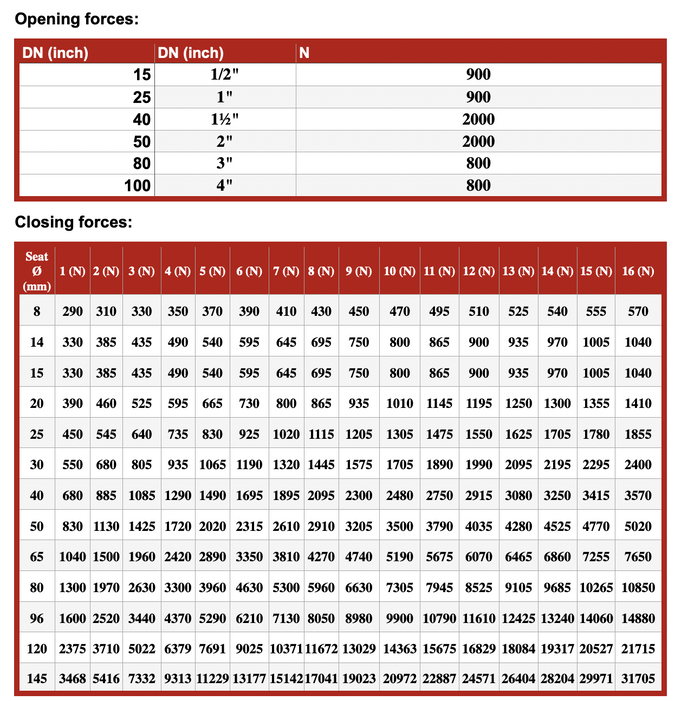
The values specified in the tables apply to a seat/plug material of PTFE. With other materials, e.g. PTFE/carbon, higher closing forces are required. Please inquire at manufacturer's. If the maximum Δp is < p2, p2 is used in the tables. observe the application limits acc. to the pressure-temperature diagram in Section 1.6. A mechanical travel stop is required in the area marked. It is provided when: Δp > 10 bar / 145 psi to Seat-Ø 15-50 mm Δp > 6 bar / 87 psi to Seat-Ø ≥ 65 mm

1.8 Pressure Temperature Diagram

Control Valve P-T-Diagram for different Bellow Configurations

2. Notes on safety

This operating manual contains fundamental information which is to be observed during installation, operation and maintenance.It must be read before installation and commissioning!
This operating manual must always be available at the place of use of the valve.
For valves which are used in potentially explosive areas, see section 3.
Installation, operation and maintenance are to be performed by qualified staff.
The area of responsibility, authority and supervision of the staff must be regulated by the customer.

It is imperative to observe warnings and signs attached directly to the ball valve and they are to be kept fully legible.
Non-observance of the notes on safety may resulting the loss of any and all claims for damages.

For example, non-observance may involve the following hazards:

  • Failure of important functions of the valve/plant.
  • Risk to people from electric, mechanical and chemical effects.
  • Risk to the environment through leaks of hazardous substances.
Hazard_Sign_PFA_Lined_Valve_Manual

General hazard symbol!
People may be put at risk.

Information_Sign_PFA_Lined_Valve_Manual

Safety symbol!
The ball valve and its function may be put at risk if this safety symbol is not observed

2.1 Intended use

GFT9 globe shut-off or control valves of the are pressure containing components in accordance with the Pressure Equipment Directive (PED) for the passage and shut-off of fluids.

The Imperium9 is designed for flow regulation and precise flow control in corrosive applications in chemical, pharmaceutical and other industries.

The valves are suitable for non-boiling liquids of group 1 in acc. with the Pressure Equipment Directive (PED). Solids can lead to increased wear, damage to sealing surfaces or to a reduction in the service life of the valve.

In case of the valve is intended for operating data other than those intended, the customer must carefully examine whether the design of the valve, accessories and materials are suitable for the new application(please consult the manufacturer).

2.2 For the customer / operator

If a valve is used, the operator must ensure that

  • hot or cold valve parts are protected by the customer against being touched
  • the valve has been properly installed in the pipe system
  • the usual flow rates are not exceeded in continuous operation.
  • an appropriate collection system is used to contain drip leaks/leaks locally and harmlessly.

This is not the manufacturer's responsibility.

Loads caused by earthquakes were not allowed for in the design.

Fire protection to DIN EN ISO 10497 is not possible (plastic lining and plastic components).

2.3 Improper operation

The operational reliability of the valve supplied is only guaranteed if it is used properly in accordance with Section 2.1 of this operating manual.

Hazard_Sign_PFA_Lined_Valve_Manual

The valve is supplied with flange caps. Do not remove them until just before installation. They protect the plastic surfaces against dirt and mechanical damage.

3. Safety notes for applications in potentially explosive areas based on the Directive 2014/34/ EC (ATEX)

The valves are intended for use in a potentially explosive area and are therefore subject to the conformity assessment procedure of the directive 2014/34/EC (ATEX).

As part of this conformity assessment, an ignition hazard analysis to EN 13463-1 to satisfy the fundamental safety and health requirements was conducted with the following result:

  • The valves do not have any ignition source of their own and can be operated both manually as well as mechanically/electrically.
  • The valves are not covered by the scope of application of the ATEX directive and therefore do not need to be identified accordingly.
  • The valves may be used in a potentially explosive area.

Supplementary notes:

  • Electric/mechanical actuators must be subjected to their own conformity assessment to ATEX.

It is imperative to observe the individual points of intended use for application in a potentially explosive are

3.1 Intended use

Improper operation, even for brief periods, may result in serious damage to the valve. In connection with explosion protection, potential sources of ignition (overheating, electrostatic and induced charges, mechanical and electric sparks) may result from improper operation. Their occurrence can only be prevented by adhering to the intended use. Furthermore, reference is made to Directive 95/C332/06 (ATEX 118a), which contains the minimum regulations for improving the occupational health and safety of workers who may be at risk from an explosive atmosphere.
A distinction is made between two cases for the use of chargeable liquids (conductivity < 10⁻⁸ S/m):

3.1.1 Chargeable liquid and non-conductive lining

Charges can occur on the lining surface, which may produce discharges inside and outside the valve.

  1. Discharges inside the valve:
    These discharges cannot cause ignitions if the valve is completely filled with medium. If the valve is not completely filled, such as during evacuation and filling, the formation of an explosive atmosphere must be prevented, e.g., by superimposing a layer of nitrogen. It is recommended to wait one hour before removing the valve from the plant to allow for the elimination of static peak charges. To safely prevent ignitions, the valve must always be completely filled with medium, or an inert gas layer must be used to exclude a potentially explosive atmosphere.
  2. Discharges outside the valve:
    Where the non-conductive lining protrudes on the sealing surfaces to the outside or comes into contact with the atmosphere, discharges may occur to nearby valves or attachments. To safely avoid explosion hazards and accidents, the atmosphere surrounding the valve must not be explosive.

3.1.2 Chargeable liquid and conductive lining

No hazardous charges can occur because charges are discharged directly via the lining and shell (surface resistance < 10⁹ Ohm, leakage resistance < 10⁶ Ohm). However, if non-conductive versions of individual components are installed in the valve, they may restrict the permitted ATEX zone and explosion subgroup despite the conductive lining of the armor plating. In such cases, it is necessary to consult the manufacturer. According to the “Technical Rules for Hazardous Substances: Avoidance of Ignition Hazards Due to Electrostatic Charges” (TRGS 727), static discharges of non-conductive linings occur only through interaction with a non-conductive medium and are therefore the responsibility of the plant operator. Static discharges are not sources of ignition stemming from the valves themselves.
Additional safety measures include:

  • The temperature of the medium must not exceed the temperature of the corresponding temperature class or the maximum permissible medium temperature as per the operating manual.
  • If the valve is heated (e.g., heating jacket), the prescribed temperature classes in the Annex must be observed.
  • To ensure safe and reliable operation, regular inspections must verify that the valve is properly maintained and kept in technically perfect condition.
  • Increased wear to the valve can be expected when conveying liquids containing abrasive constituents, requiring shorter inspection intervals than usual.
  • Actuators and electric peripherals, such as temperature, pressure, and flow sensors, must comply with valid safety requirements and explosion protection provisions.
  • The valve must be grounded, which can be achieved using pipe screws with tooth lock washers. Otherwise, grounding must be ensured by other means, such as a cable link.
  • Attachments such as actuators, position controllers, and limit switches must comply with relevant safety regulations concerning explosion protection and, if required, be designed in accordance with ATEX.
  • Special attention must be paid to the appropriate safety and explosion protection notes in the respective operating manuals.
  • Plastic-lined valves must not be operated with carbon disulfide.

4. Safety note for valves, certified to Clean Air Act (TA Luft)

The validity of the Certificate/Manufacturer Declaration depends on the operating instructions being read and observed.

  • Carry out regular maintenance intervals and check the tightness of the screw connections, tightening them as necessary.

5. Transport, storage and disposal

Handle the goods being transported with care. During transport protect the valve against impacts and collisions.

Directly after receipt of the goods, check the consignment for completeness and any in-transit damage.

Do not damage paint protection.

Hazard_Sign_PFA_Lined_Valve_Manual

For all transport work, observe generally accepted engineering practice and the accident prevention regulations

Information_Sign_PFA_Lined_Valve_Manual

The valve is supplied with flange caps. Do not remove them until just before installation. They protect the plastic surfaces against dirt and mechanical damage.

5.1 Storage

If the valve is not installed immediately after delivery, store them properly.
The valves be stored in a dry, vibration-free and well ventilated room at as constant a temperature as possible.
Protect elastomers against UV light.
In general, a storage period of 10 years should not be exceeded.

5.2 Return consignments

It is imperative to enclose a safety information sheet / general safety certificate on the field of application with the return consignment.
Contact the Manufacturer for more Information in that regard.
Safety precautions and decontamination measures are to be mentioned.

Hazard_Sign_PFA_Lined_Valve_Manual

Valves which have conveyed aggressive or toxic media rinse
and clean before being returned to the manufacturer's works

5.3 Disposal

Parts of the valve may be contaminated with medium which is detrimental to health and the environment and therefore cleaning is not sufficient.

Hazard_Sign_PFA_Lined_Valve_Manual

Risk of personal injury or damage to the environment due to the medium!

Wear protective clothing when work is performed on the valve.
Prior to the disposal of the valve:

  • Collect any medium, etc. which has escaped and dispose of it in accordance with the local regulations.
  • Neutralise any medium residues in the valve.
  • Separate valve materials (plastics, metals, etc.) and dispose of them in accordance with the local regulations.

6.Installation

  • Examine valve for in-transit damage, damaged sample valves must not be installed.
  • Before installation the valve and the connecting pipe must be carefully cleaned to remove any dirt, especially hard foreign matter.
  • During installation, pay attention to the correct tightening torque, aligned pipes and tension-free assembly.
  • The all-round gap between the body and the cover must remain constant so that a centric position of the plug in relation to the seat is guaranteed.
  • Operation during maintenance work can be continued with a bypass around the control valve.
  • Depending on the kv-value, the free cross section in the valve may be much smaller than the cross section of the nominal size. To prevent clogging, the pipe must be carefully cleaned upstream of the valve
Hazard_Sign_PFA_Lined_Valve_Manual

Ensure that a remotely actuated actuator cannot be accidentally switched on.

6.1 Flange caps and gaskets

Leave protective caps on the flanges until just prior to installation.

Where there is a particularly high risk of damage to the plastic sealing surfaces, e.g. if the mating flanges are made of metal or enamel, PTFE-lined gaskets with a metal inlay should be used. Contact the Manufacturer for further discussion.

6.2 Direction of flow and installation position

Normally the valve is installed in a horizontal pipe with the handwheel on top. The valve can also be installed vertically facing downwards or at an angle. However, that is only admissible if there is no risk of the bellows becoming contaminated.
Inclined positions of the actuator are only admissible after consultation with the manufacturer. In this case a support structure may have to be provided for the
actuator.

6.3 Grounding

The valve must be grounded. This can be achieved in the simplest way via the pipe screws using tooth lock washers. One pipe screw per flange is underlaid with toothed disks.

Upon customer request a set screw M6 is attached to each flange with a hex nut and washer as an additional earthing connection.

Otherwise grounding must be ensured by different measures e.g. a cable link.

6.4 Test pressure

The test pressure PT of a valve must not exceed the value of 1.5 x PS(PN) as per the identification of the valve.

6.5 Monitoring connection

If the cover flange has a screw-in fitting for an alarm connection, the latter must also be connected or the screw-in fitting has to be sealed. Otherwise, medium could escape if the bellows became defective.
In order to ensure leak monitoring, GFT9 recommends the combination of the safety stuffing box with a warning connection.

7. Operation

7.1 Initial commissioning

Normally, the valves have been tested for leaks with air or water. Prior to initial operation check cover screws. For tightening torques, see Section 1.6!

To prevent leaks, all connection screws should be retightened after the initial loading of the valve with operating pressure and operating temperature. For tightening torques, see Section 1.6.

Hazard_Sign_PFA_Lined_Valve_Manual

Unless otherwise agreed there could be residual amounts of water in the flow section of the valve. This could result in a possible reaction with the medium.

7.2 Improper operation and their consequences

  • Crystallisation must be prevented, e.g. by heating. In extreme cases blocking or a leak may occur.
  • Increased wear occurs in operation with solids contents.
  • Operation during cavitation leads to increased wear.
  • Non-observance of the pressure-temperature diagram can lead to damage.
  • If no monitoring is provided by the warning connection, do not tighten safety stuffing box. Otherwise any leak cannot be seen.
  • Do not subject the handwheel to heavy loads; the lever or valve may be damaged

7.3 Shutdown

The local regulations are to be observed when dismantling the valve!

After dismantling, immediately protect the valve flanges against mechanical damage by using flange caps. See also Section 6.1.
Make sure that a remote-controlled actuator cannot be switched on by accident.

Hazard_Sign_PFA_Lined_Valve_Manual

Prior to undoing the flange connection ensure, that the plant is depressurised and emptied!

Hazard_Sign_PFA_Lined_Valve_Manual

Prior to starting any repair work, the valve is to be thoroughly cleaned. Medium residue may be in the valve even if it has been properly drained and flushed.

8. Malfunctions

Flange connection valve/pipe is leaking

  1. Retighten the flange screws to a tightening torque according to Section 1.2.
  2. If this does not remedy the leak, the recommended torques may be exceeded by 10%.
  3. If this also fails to stop the leak, dismantle and inspect the valve.

Flange connection body/cover is leaking

  • Retighten body screws. Following see paragraph "Flange connection ball valve/pipe is leaking".

Packing is leaking

  • Retighten packing nut (DN 15, 20) or hex. nuts of the packing gland follower in line with the details in Section1.3.
  • Then dismount the valve as quickly as possible and repair:
    Replace bellows.
    Replace plug and/or seat.
    Replace packing rings

Monitoring connection reports a rise in pressure or a leak

Replace bellows.
Replace plug and/or seat.
Replace packing rings.

  • Valve can only be moved with difficulty: Is the stuffing box tightened too much?
  • Valve does not close tight: Are there any solids between seat and plug? Are the sealing surfaces of the seat or plug dam-
    aged?
  • The flow rate is too high or too low.
  • The performance curve is not correct.
  • The valve cavitates.

Do the rated data according to the data sheet or works certificate match the data of the plant?
Are the correct seat and plug installed? See markings on the seat and plug and compare them with the name plate and the data sheet.

9. Maintenance

  • All repair work is to be performed by qualified personnel using the appropriate tools.
  • For the arrangement, designation and item numbers of all parts of the valve, see Section 10.
  • Spare parts are to be ordered with all the details in acc. with the valve identification.
  • Only original spare parts may be installed.
  • To prevent leaks, a regular check of the connection screws should be made in line with the operating requirements.
  • For tightening torques, see Section 1.2

Hazard_Sign_PFA_Lined_Valve_Manual

Make sure that when working on the sampling valve it is drained. See also Section 7.4

9.1 Dismantling

9.1.1 Maintenance of the upper section

This mainly involves the following work:

  • Replacing the plug.
  • Replacing the bellows.
  • Inspecting the metal parts of the upper section and replacing them if necessary.

The entire dismantling and assembly procedure is described below. If only partial assembly is required, this can be derived from the text.

9.1.2 Dismantling Plug

Step 1:
Move plug into open position if the actuator is mounted. Then, remove cover nuts and screws. Then pull cover vertically out of the body.
Step 2:
Undo bellows with plug by hand or use a strap wrench. Right-hand thread.
Step 3:
With the heavy-duty bellows do not remove the support rings and the support disc.
Step 4:
Pull round cord out of the plug with a pair of pliers.
Step 5:
Unscrew plug by hand or with a strap wrench. Right-hand thread.
Step 6:
Check whether the seat is still OK. If not: Replace. See Section 9.2.2

9.1.3 Replace packing rings.

Step 1:
Only replace packing rings and thrust ring when necessary.
Step 2:
Dismantling and assembly are described in the following, once the upper part has already been pulled out of the body.
DN 15 and DN 20 (½“.– ¾“)
Step 3:
Remove spring-type slotted pin, unscrew handwheel and packing nut.
Step 4:
Remove thrust ring.Then turn spindle with guide and, when thread is free, pull downwards.
Step 5:
Replace packing rings.
Step 6:
Insert thrust ring and packing nut.
Step 7:
Push spindle with guide upwards. Make sure that the round head rivet lies in the groove of the cover. Then screw spindle/guide into the cover.
Step 8:
Tighten packing nut slightly. Screw on handwheel and force in spring-type slotted pin.

DN 25 - DN 65 (1" -2½“):
Step 1:
Remove locknut and unscrew handwheel hub with handwheel (the plain bearings may fall out of the cover).
Step 2:
Undo stuffing box screw fittings
Step 3:
Force out spring-type slotted pin.
Step 4:
Pull out stem downwards.
Step 5:
Remove lower plain bearing, packing gland follower and thrust
ring.
Step 6:
Replace packing rings
Step 7:
Insert thrust ring and packing gland follower
Step 8:
Before pushing up the stem, push plain bearing and ring over the stem.
Step 9:
Push up stem and force in spring-type slotted pin
Step 10:
Tighten packing gland follower slightly. Screw handwheel hub with handwheel
into the plain bearings.
Step 11:
Open the valve completely by turning the handwheel counter-clockwise.
Step 12:
Secure with locknut(torque: 442.5 lb-in (50 Nm))


DN 80 and DN 100 (3" and 4"):
Step 1:
Unscrew groove nuts off the handwheell hub.
Step 2:
Now continue as described under DN 25 - DN 60.

9.2 Assembly

9.2.1 Installing plug

Step 1:
Screw bellows without lubricant onto the stem and tighten by hand. Check whether the new plug fits into the seat. Make sure that neither the seat nor the plug is damaged.
Step 2:
Screw plug or cap with plug without lubricant on the bellows and tighten by hand.
Step 3:
Press round cord down to 10 mm into the plug or cap. This facilitates the next dismantling operation
Step 3:
Install stem with bellows and plug without lubricant into the cover.
Step 4:
Carefully lower upper section into the body.
Step 5:
Install cover screw fittings. For tightening torques, see Section 1.3.

9.2.2 Replacing the seat

Step 1:
A screw-in tool is required for assembling and dismantling the seat. The article numbers for the individual nominal sizes are listed in Section 1.
Step 2:
The new seat is to be carefully protected prior to assembly. The sealing edge and the sealing surface for the plug must not be damaged.

Step 3:
Remove the upper part of the valve as described in Section 9.1.1. Screw the seat out of the body with the screw-in tool. Right-hand thread.
Step 4:
Carefully clean the sealing surface in the body and check for damage.
Step 5:
If there is any damage, you can try to rework the sealing surface.
Step 6:
Screw the new seat without lubricant into the body using the screw-in tool. For tightening torques, see Section 1.3.
Step 7:
Further assembly as described in Section 9.2.1

9.2.3 V-Plug

In contrast to the normal valve plug, the seat diameter is smaller than the V-plug diameter.
The V-plug is pushed firmly over the resilient sealing lip of the valve seat. This seals the plug.

9.3 Setting the travel stop


To ensure the valve closes tight, a distance between the travel stop and cover must be observed:

  • DN 15 - 50 (½“.– 2“) : 0.5 mm
  • DN 65 - 150 (2½“ – 6“) : 1.0 mm

If these distances are not correct, the travel stop must be reset:

Step 1:
Close valve and remove protection bellows.
Step 2:
Move travel stop to the correct distance.
Step 3:
Tighten lock nut.

9.4 Mounting the actuator

Assembly of the actuator varied depending on the make and type. The operating manuals for actuators, positioners and other accessories must be observed. As regards the process valve, special attention is to
be paid to the following:

  • The stem 800 must under no circumstances by turned to adapt to the coupling. If turned counterclockwise, it would otherwise turn out of
    the metal core of the bellows.
  • The actuator manufacturers prescribe that the valve is moved into the closed position when the coupling is mounted. In this closed position many bellows are pre-tensioned in the valve. They would possibly open the valve again. Therefore, the stem is to be kept in the closed position when the coupling is mounted.

10. Dimensional Drawings

10.1 Dimensional Measurements DIN

Size L H ød øk øD Bolting Weight
DN 15 130 mm 130 mm 45 mm 65 mm 95 mm 4 x 14 (M12) 6 kg
DN 20 150 mm 130 mm 58 mm 75 mm 105 mm 4 x 14 (M12) 6 kg
DN 25 160 mm 185 mm 68 mm 85 mm 115 mm 4 x 14 (M12) 11 kg
DN 40 200 mm 225 mm 88 mm 110 mm 150 mm 4 x 18 (M16) 16 kg
DN 50 230 mm 230 mm 102 mm 125 mm 165 mm 4 x 18 (M16) 19 kg
DN 80 310 mm 340 mm 138 mm 160 mm 200 mm 8 x 18 (M16) 39 kg
DN 100 350 mm 350 mm 158 mm 180 mm 220 mm 8 x 18 (M16) 44 g

10.2 Dimensional Measurements ANSI

Size L1 H ød øk øD Bolting Weight
NPS ½" 130 mm 130 mm 34,9 mm 60,3 mm 88,9 mm 4 x 15.9 6 kg
NPS ¾" 130 mm 130 mm 42,9 mm 69,8 mm 98,4 mm 4 x 15.9 6 kg
NPS 1" 160 mm 185 mm 50,8 mm 79,4 mm 108 mm 4 x 15.9 11 kg
NPS 1½" 200 mm 225 mm 73 mm 98,4 mm 127 mm 4 x 15.9 16 kg
NPS 2" 230 mm 230 mm 92,1 mm 121 mm 152,4 mm 4 x 19 19 kg
NPS 3" 310 mm 340 mm 127 mm 152,4 mm 190,5 mm 4 x 19 39 kg
NPS 4" 350 mm 350 mm 157,2 mm 190 mm 228,6 mm 8 x 19 44 kg

11. Sectional Drawing

Pos. Item Material
1 Body 1.0619 or 1.4308/1.4408/1.4409 | A216/WCB,CF8/CF8M/CF3M
2 Lining PFA Perfluoralkoxy (standard) or PFA-LantistaticF-L (on request)
3.1 Trim Variant 1 Plug (TFM-PTFE) | Seat (TFM-PTFE) | Bellow (PFA HD-bellow (standard))
3.2 Trim Variant 2 V-Plug (TFM-PTFE) | Seat (TFM-PTFE) | Bellow (PFA HD-bellow)
3.3 Trim Variant 3 U Plug (TFM-PTFE) | Seat (TFM-PTFE) | Bellow (PFA HD-bellow (standard))
4 Bellow PFA

12. Declaration of Conformity

Konformitätserklärung 2014/68/EU
Declaration of Conformity 2014/68/EU

Product Control Valve
Design Globe Control Valve
Serial number
Size DN 15 - DN 100 | NPS 1½" - NPS 4"
EU-Directive 2014/68/EU
Applied Technical Specification DIN EN IS0 12100 AD 2000
Surveillance Procedure 2014/68/EU, TÜV Rheinland Industrie Service GmbH
Notified Body for Pressure ID-No. 0035
Equipment
Conformity assessment. 2014/68/EU / 2014/68/EU
Procedure
Marking 2014/68/EU¹⁾ ≥ DN 25, ≥ 1“


Advanced Fluoropolymer Devices GmbH confirms that the basic requirements of the above specified directives and standards have been fullied
¹⁾ For sizes not listed a marking is not permissible.

Kempen, 17.12.2024

K. Schalm