Advanced Fluoropolymer Devices GmbH
Precision Manufacturing Meets Transfer Molding
Installation and Operating Manual
Diaphragm Valve
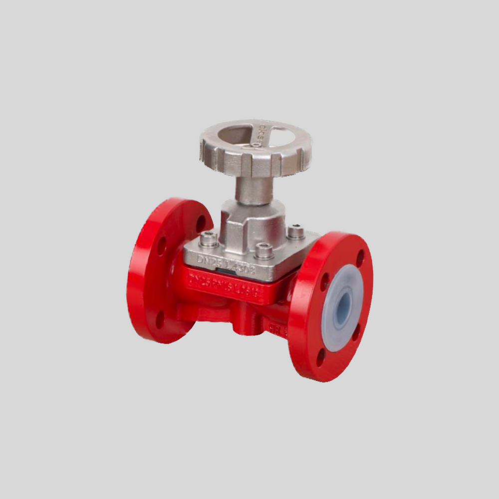
PFA Lined Diaphragm Valve
Membron9
This comprehensive manual provides detailed instructions for safe transport, installation, operation, and routine maintenance of your equipment.
Please review all sections carefully before proceeding. Keep this manual accessible for future reference.
Important Safety Notice
Carefully observe these operating instructions before transport, installation, operation, and maintenance!
Failure to follow proper procedures may result in equipment damage, personal injury, or voided warranty.
Manual Information
- Document Version: 1.0
- Last Updated: July 25, 2026
- Document Type: Installation and Operating Manual
- Language: English
Quick Reference Guide
📋 Before You Start
🚚 Transport Guidelines
⚙️ Installation Process
🔧 Operation Manual
🛠️ Maintenance Schedule
📞 Support Contact
| Parameter | Value |
|---|---|
| Name | Membron9 |
| Design norm | DIN/ISO | ANSI |
| Size | DN15-150 | NPS ½"-6" |
| Flange dimensions | DIN 2501 (PN 16) | ASME B16.10 (Class 150-RF LP) |
| Face to face dimensions | PN (EN 558-1), Series 1 | ANSI-B-16.5 |
| Lining | PFA, PFA/AS, PVDF |
| Body | WCB/PFA, CF8/ SS 304 , 1.4401 |
| Pressure | Depending on Size (see P-T Diagram below) |
| Custom | Various Actuation Types, Coatings |
| Certificates | EU Pressure Equipment Directive 2014/68/EU |
DIN Weight Specifications
| Size DIN | Weight |
|---|---|
| DN 15 | 7,5 kg |
| DN 20 | 9,8 kg |
| DN 25 | 11,2 kg |
| DN 40 | 18,8 kg |
| DN 50 | 21,7 kg |
| DN 65 | 22,5 kg |
| DN 80 | 23,5 kg |
| DN 100 | 30 kg |
| DN 125 | 40 kg |
| DN 150 | 44 kg |
ANSI Weight Specifications
| Size ANSI | Weight |
|---|---|
| NPS ½" | 9,5 kg |
| NPS ¾" | 7,3 kg |
| NPS 1" | 10,9 kg |
| NPS 1½" | 18,5 kg |
| NPS 2" | 21,4 kg |
| NPS 2½" | 22,1 kg |
| NPS 3" | 23,5 kg |
| NPS 4" | 28,5 kg |
| NPS 6" | 37 kg |
DIN Pipe Screws
| Size | Screws | Tightening Torque [Nm] [Nm/lbs] |
|---|---|---|
| DN 15 | 4 x M12 | 6 |
| DN 20 | 4 x M12 | 8 |
| DN 25 | 4 x M12 | 10 |
| DN 40 | 4 x M16 | 20 |
| DN 50 | 4 x M16 | 26 |
| DN 65 | 4 x M16 | 26 |
| DN 80 | 8 x M16 | 25 |
| DN 100 | 8 x M16 | 35 |
| DN 125 | 8 x M20 | 55 |
| DN 150 | 8 x M20 | 65 |
ANSI Pipe Screws
| Size | Screws | Tightening Torque [Nm] [Nm/lbs] |
|---|---|---|
| NPS ½" | 4 x ½“ | 45/5 |
| NPS ¾" | 4 x ½“ | 55/6 |
| NPS 1" | 4 x ½“ | 70/8 |
| NPS 1½" | 4 x ½“ | 135/15 |
| NPS 2" | 4 x ⅝“ | 220/15 |
| NPS 2½" | 4 x ⅝“ | 400/45 |
| NPS 3" | 4 x ⅝“ | 400/45 |
| NPS 4" | 8 x ⅝“ | 310/35 |
DIN Body Screws
| Size | Screws | Tightening Torque [Nm] [Nm/lbs] |
|---|---|---|
| DN 15 | 4 x M12 | 35/310 |
| DN 20 | 4 x M12 | 35/310 |
| DN 25 | 4 x M12 | 35/310 |
| DN 40 | 4 x M16 | 45/398 |
| DN 50 | 4 x M16 | 45/398 |
| DN 65 | 4 x M16 | 45/398 |
| DN 80 | 8 x M16 | 50/442 |
| DN 100 | 8 x M16 | 60/531 |
| DN 125 | 8 x M20 | 150/1330 |
| DN 150 | 8 x M20 | 150/1330 |
ANSI Body Screws
| Size | Screws | Tightening Torque [Nm] [Nm/lbs] |
|---|---|---|
| NPS ½" | 4 x M12 | 310/35 |
| NPS ¾" | 4 x M12 | 310/35 |
| NPS 1" | 4 x M12 | 310/35 |
| NPS 1½" | 4 x M16 | 398/45 |
| NPS 2" | 4 x M16 | 398/45 |
| NPS 2½" | 8 x M16 | 398/45 |
| NPS 3" | 8 x M20 | 442/50 |
| NPS 4" | 12 x M24 | 531 /80 |
DIN Actuation Torque
| Size | Actuation Torque [Nm / Lbs] |
|---|---|
| DN 15 | 80 |
| DN 20 | 85 |
| DN 25 | 115 |
| DN 40 | 155 |
| DN 50 | 155 |
| DN 65 | 190 |
| DN 80 | 200 |
| DN 100 | 245 |
| DN 125 | 300 |
| DN 150 | 360 |
ANSI Actuation Torque
| Size | Actuation Torque [Nm / Lbs] |
|---|---|
| NPS ½" | 80 |
| NPS ¾" | 85 |
| NPS 1" | 115 |
| NPS 1½" | 155 |
| NPS 2" | 155 |
| NPS 2½" | 190 |
| NPS 3" | 200 |
| NPS 4" | 245 |
| NPS 6" | 360 |
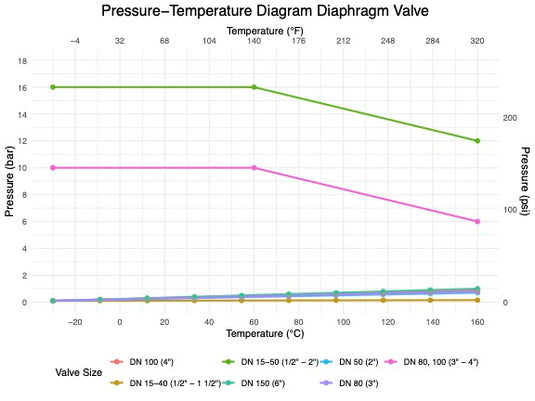
P-T Diagram for the Diphragm Valve


10. Dimensional Drawings
10.1 Dimensional Measurements DIN
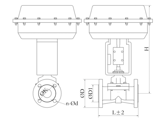
| Size | L | ød | øk | øD | Bolting | Weight |
|---|---|---|---|---|---|---|
| DN 15 | 130 mm | 45 mm | 65 mm | 95 mm | 4 x 14 (M12) | 7,5 kg |
| DN 20 | 150 mm | 58 mm | 75 mm | 105 mm | 4 x 14 (M12) | 9,8 kg |
| DN 25 | 160 mm | 68 mm | 85 mm | 115 mm | 4 x 14 (M12) | 11,2 kg |
| DN 40 | 200 mm | 88 mm | 110 mm | 150 mm | 4 x 18 (M16) | 18,8 kg |
| DN 50 | 230 mm | 102 mm | 125 mm | 165 mm | 4 x 18 (M16) | 21,7 kg |
| DN 65 | 290 mm | 122 mm | 145 mm | 185 mm | 4 x 18 (M16) | 22,5 kg |
| DN 80 | 310 mm | 138 mm | 160 mm | 200 mm | 8 x 18 (M16) | 23,5 kg |
| DN 100 | 350 mm | 158 mm | 180 mm | 220 mm | 8 x 18 (M16) | 30 kg |
| DN 125 | 400 mm | 188 mm | 210 mm | 250 mm | 8 x 18 (M16) | 40 kg |
| DN 150 | 480 mm | 212 mm | 240 mm | 285 mm | 8 x 22 (M20) | 44 kg |
10.2 Dimensional Measurements ANSI
| Size | L | ød | øk | øD | Bolting | Weight |
|---|---|---|---|---|---|---|
| NPS ½" | 150 mm | 34,9 mm | 60,3 mm | 88,9 mm | 4 x 15.9 | 9,5 kg |
| NPS ¾" | 130 mm | 42,9 mm | 69,8 mm | 98,4 mm | 4 x 15.9 | 7,3 kg |
| NPS 1" | 160 mm | 50,8 mm | 79,4 mm | 108 mm | 4 x 15.9 | 10,9 kg |
| NPS 1½" | 200 mm | 73 mm | 98,4 mm | 127 mm | 4 x 15.9 | 18,5 kg |
| NPS 2" | 230 mm | 92,1 mm | 121 mm | 152,4 mm | 4 x 19 | 21,4 kg |
| NPS 2½" | 290 mm | 104,8 mm | 139,7 mm | 177,8 mm | 4 x 19 | 22,1 kg |
| NPS 3" | 310 mm | 127 mm | 152,4 mm | 190,5 mm | 4 x 19 | 23,5 kg |
| NPS 4" | 350 mm | 157,2 mm | 190 mm | 228,6 mm | 8 x 19 | 28,5 kg |
| NPS 6" | 480 mm | 216 mm | 241 mm | 279 mm | 8 x 22.2 | 37 kg |
11. Sectional Drawing
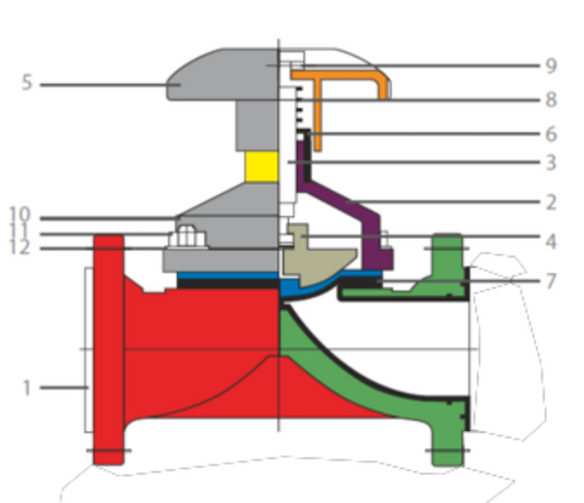
| Pos. | Item | Material |
|---|---|---|
| 1 | Lined Body | WCB, CF8 - PFA Lined |
| 2 | Bonnet | WCB, CF8 |
| 3 | Spindle | SS316 |
| 4 | Compressor Pin Type | WCB, CF8 |
| 5 | Handwheel | CF8 |
| 6 | Opening Indicator Sleeve | HDPE |
| 7 | Diaphragm (pin Type) | PTFE Backed with EPDM |
| 8 | Compression Spring | Stainless Steel |
| 9 | Dowell Pin Spring | Steel |
| 10 | Stud | Stainless Steel |
| 11 | Nut | Stainless Steel |
| 12 | Plain Washer | Stainless Steel |