Advanced Fluoropolymer Devices GmbH
Precision Manufacturing Meets Transfer Molding

Installation and Operating Manual

Swing Check Valve

PFA Lined Swing Check Valve

Vibron9

This comprehensive manual provides detailed instructions for safe transport, installation, operation, and routine maintenance of your equipment.
Please review all sections carefully before proceeding. Keep this manual accessible for future reference.
⚠️

Important Safety Notice

Carefully observe these operating instructions before transport, installation, operation, and maintenance!

Failure to follow proper procedures may result in equipment damage, personal injury, or voided warranty.

Manual Information

  • Document Version: 1.0
  • Last Updated: July 25, 2026
  • Document Type: Installation and Operating Manual
  • Language: English

Quick Reference Guide

📋 Before You Start
🚚 Transport Guidelines
⚙️ Installation Process
🔧 Operation Manual
🛠️ Maintenance Schedule
📞 Support Contact

1 Technical Data

1.1 Manufacturer Information

Advanced Fluoropolymer Devices GmbH
Hooghe Weg 16, 47906 Kempen, Germany
Email: sales@gft9.shop
Web: http://gft9.shop
Phone: +49 2152 9148591

1.2 Product Overview

Parameter Value
Name Vibron9
Design norm DIN | ANSI
Size DN 40-400 | NPS 1 ½"-16"
Flange dimensions DIN EN 1092-1, PN 16 | ANSI B 16.5 Cl. 150/B16.42
Face to face dimensions DIN EN 558-1 Row 20, ISO 5752 | API 609/BS 5155
Lining PFA Lining 3mm - 5mm thickness), PFA Conducting
Body 1.0619 or 1.4308/1.4408/1.4409 | A216/WCB,CF8/CF8M/CF3M
Pressure 0.1 mbar vacuum to 16 bar
Temperature range -40°C up to +150°C
Leakage rate Leakage Rate D
Custom PTFE solid retainer ring
Quality Body 15bar, Back Seat 2bar, Spark Test 15kV DC

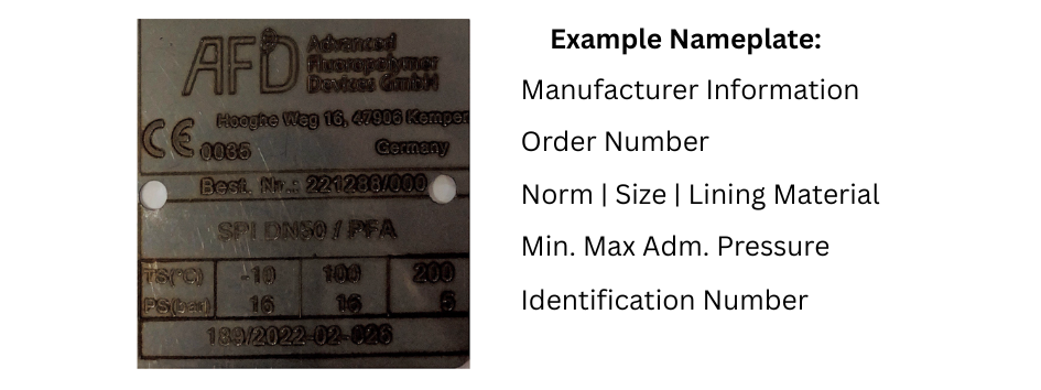
1.3 Type plate, conformity and body markings

Exemplary_Nameplate_PFA_Lined_Valve_Size_Pressure_Temperature_Valve_Type_Order_No._Identification_Number

Type Plate
The stainless steel name plate is undetachably riveted to the body. If the operator attaches his identification, it must be ensured that the valve matches the application inquestion.

Body identification:
The following are visible on the body according to DIN EN 19 and AD 2000 A4:

  • Nominal size
  • Rated pressure
  • Body material
  • Manufacturer's identification
  • Melt number/Foundry identification
  • Foundry date

1.4 Weight DIN | ANSI

DIN Weight Specifications
Size DIN Weight
DN 40 2 kg
DN 50 3 kg
DN 80 5 kg
DN 100 7 kg
DN 150 11 kg
DN 200 19 kg
DN 250 28 kg
DN 300 39 kg
DN 350 65 kg
DN 400 90 kg
ANSI Weight Specifications
Size ANSI Weight
NPS 1 1/2" 2 kg
NPS 2" 3 kg
NPS 3" 5 kg
NPS 4" 7 kg
NPS 6" 11 kg
NPS 8" 19 kg
NPS 10" 28 kg
NPS 12" 39 kg
NPS 14" 65 kg
NPS 16" 90 kg

1.8 Pressure Temperature Diagram

P-T-Diagram for the Swing Check Valve

2. Notes on safety

This operating manual contains fundamental information which is to be observed during installation, operation and maintenance. It must be read before installation and commissioning!
This operating manual must always be available at the place of use of the valve.
For valves which are used in potentially explosive areas, see section 3.
Installation, operation and maintenance are to be performed by qualified staff.
The area of responsibility, authority and supervision of the staff must be regulated by the customer.

It is imperative to observe warnings and signs attached directly to the swing check valve and they are to be kept fully legible.
Non-observance of the notes on safety may result in the loss of any and all claims for damages.
For example, non-observance may involve the following hazards:

  • Failure of important functions of the valve/plant.
  • Risk to people from electric, mechanical and chemical effects.
  • Risk to the environment through leaks of hazardous substances.
Hazard_Sign_PFA_Lined_Valve_Manual

General hazard symbol!
People may be put at risk.

Information_Sign_PFA_Lined_Valve_Manual

Safety symbol!
The swing check valve and its function may be put at risk if this safety symbol is not observed.

2.1 Intended use

GFT9 swing check valves are self-acting non-return components in accordance with the Pressure Equipment Directive (PED) for the passage of fluids in the direction of the flow arrow on the body and for the shut-off of fluids in the opposite direction. The shut-off operation is initiated by the weight of the disc as delivery decreases. Depending on the installation position, differential pressure and medium, a completely tight shut-off cannot be guaranteed in every operating state (Leakage Rate D).

The valves are of wafer (sandwich) design in accordance with DIN EN 593, for installation between two pipe flanges to DIN EN 1092-1 PN 16 or ASME B16.5 Class 150 / B16.42. They are suitable for vapours, gases and liquids of group 1 in accordance with the PED and have a corrosion-resistant plastic lining.

Sealing tightness depends on the differential (back) pressure across the closed disc:

  • Δp up to 2.76 bar (0-40 psi): leakage rate 5-10 cm³/min
  • Δp 2.77-5.1 bar (41-74 psi): leakage rate 3-5 cm³/min
  • Δp above 5.1 bar (above 74 psi): tight, 0 cm³/min

A completely tight shut-off is therefore only achieved at differential pressures above 5.1 bar.

Solids can lead to increased wear, damage to sealing surfaces or to a reduction in the service life of the valve. In case the valve is intended for operating data other than those intended, the customer must carefully examine whether the design of the valve, accessories and materials are suitable for the new application. (Please consult the manufacturer.)

2.2 For the customer / operator

If a valve is used, the operator must ensure that

  • hot or cold valve parts are protected by the customer against being touched
  • the valve has been properly installed in the pipe system
  • the usual flow rates are not exceeded in continuous operation.
  • an appropriate collection system is used to contain drip leaks/leaks locally and harmlessly.

This is not the manufacturer's responsibility.

Loads caused by earthquakes were not allowed for in the design.

Fire protection to DIN EN ISO 10497 is not possible (plastic lining and plastic components).

2.3 Improper operation

The operational reliability of the valve supplied is only guaranteed if it is used properly in accordance with Section 2.1 of this operating manual.

Hazard_Sign_PFA_Lined_Valve_Manual

The valve is supplied with flange caps. Do not remove them until just before installation. They protect the plastic surfaces against dirt and mechanical damage.

3. Safety notes for applications in potentially explosive areas based on the Directive 2014/34/ EC (ATEX)

The valves are intended for use in a potentially explosive area and are therefore subject to the conformity assessment procedure of the directive 2014/34/EC (ATEX).

As part of this conformity assessment, an ignition hazard analysis to EN 13463-1 to satisfy the fundamental safety and health requirements was conducted with the following result:

  • The valves do not have any ignition source of their own and can be operated both manually as well as mechanically/electrically.
  • The valves are not covered by the scope of application of the ATEX directive and therefore do not need to be identified accordingly.
  • The valves may be used in a potentially explosive area.

Supplementary notes:

  • Electric/mechanical actuators must be subjected to their own conformity assessment to ATEX.

It is imperative to observe the individual points of intended use for application in a potentially explosive are

3.1 Intended use

Improper operation, even for brief periods, may result in serious damage to the valve. In connection with explosion protection, potential sources of ignition (overheating, electrostatic and induced charges, mechanical and electric sparks) may result from improper operation. Their occurrence can only be prevented by adhering to the intended use. Furthermore, reference is made to Directive 95/C332/06 (ATEX 118a), which contains the minimum regulations for improving the occupational health and safety of workers who may be at risk from an explosive atmosphere.
A distinction is made between two cases for the use of chargeable liquids (conductivity < 10⁻⁸ S/m):

3.1.1 Chargeable liquid and non-conductive lining

Charges can occur on the lining surface, which may produce discharges inside and outside the valve.

  1. Discharges inside the valve:
    These discharges cannot cause ignitions if the valve is completely filled with medium. If the valve is not completely filled, such as during evacuation and filling, the formation of an explosive atmosphere must be prevented, e.g., by superimposing a layer of nitrogen. It is recommended to wait one hour before removing the valve from the plant to allow for the elimination of static peak charges. To safely prevent ignitions, the valve must always be completely filled with medium, or an inert gas layer must be used to exclude a potentially explosive atmosphere.
  2. Discharges outside the valve:
    Where the non-conductive lining protrudes on the sealing surfaces to the outside or comes into contact with the atmosphere, discharges may occur to nearby valves or attachments. To safely avoid explosion hazards and accidents, the atmosphere surrounding the valve must not be explosive.

3.1.2 Chargeable liquid and conductive lining

No hazardous charges can occur because charges are discharged directly via the lining and shell (surface resistance < 10⁹ Ohm, leakage resistance < 10⁶ Ohm). However, if non-conductive versions of individual components are installed in the valve, they may restrict the permitted ATEX zone and explosion subgroup despite the conductive lining of the armor plating. In such cases, it is necessary to consult the manufacturer. According to the “Technical Rules for Hazardous Substances: Avoidance of Ignition Hazards Due to Electrostatic Charges” (TRGS 727), static discharges of non-conductive linings occur only through interaction with a non-conductive medium and are therefore the responsibility of the plant operator. Static discharges are not sources of ignition stemming from the valves themselves.
Additional safety measures include:

  • The temperature of the medium must not exceed the temperature of the corresponding temperature class or the maximum permissible medium temperature as per the operating manual.
  • If the valve is heated (e.g., heating jacket), the prescribed temperature classes in the Annex must be observed.
  • To ensure safe and reliable operation, regular inspections must verify that the valve is properly maintained and kept in technically perfect condition.
  • Increased wear to the valve can be expected when conveying liquids containing abrasive constituents, requiring shorter inspection intervals than usual.
  • Actuators and electric peripherals, such as temperature, pressure, and flow sensors, must comply with valid safety requirements and explosion protection provisions.
  • The valve must be grounded, which can be achieved using pipe screws with tooth lock washers. Otherwise, grounding must be ensured by other means, such as a cable link.
  • Attachments such as actuators, position controllers, and limit switches must comply with relevant safety regulations concerning explosion protection and, if required, be designed in accordance with ATEX.
  • Special attention must be paid to the appropriate safety and explosion protection notes in the respective operating manuals.
  • Plastic-lined valves must not be operated with carbon disulfide.

4. Safety note for valves, certified to Clean Air Act (TA Luft)

The validity of the Certificate/Manufacturer Declaration depends on the operating instructions being read and observed.

  • Carry out regular maintenance intervals and check the tightness of the screw connections, tightening them as necessary.

5. Transport, storage and disposal

Handle the goods being transported with care. During transport protect the valve against impacts and collisions.

Directly after receipt of the goods, check the consignment for completeness and any in-transit damage.

Do not damage paint protection.

Hazard_Sign_PFA_Lined_Valve_Manual

For all transport work, observe generally accepted engineering practice and the accident prevention regulations

Information_Sign_PFA_Lined_Valve_Manual

The valve is supplied with flange caps. Do not remove them until just before installation. They protect the plastic surfaces against dirt and mechanical damage.

5.1 Storage

If the valve is not installed immediately after delivery, store them properly.
The valves be stored in a dry, vibration-free and well ventilated room at as constant a temperature as possible.
Protect elastomers against UV light.
In general, a storage period of 10 years should not be exceeded.

5.2 Return consignments

It is imperative to enclose a safety information sheet / general safety certificate on the field of application with the return consignment.
Contact the Manufacturer for more Information in that regard.
Safety precautions and decontamination measures are to be mentioned.

Hazard_Sign_PFA_Lined_Valve_Manual

Valves which have conveyed aggressive or toxic media rinse
and clean before being returned to the manufacturer's works

5.3 Disposal

Parts of the valve may be contaminated with medium which is detrimental to health and the environment and therefore cleaning is not sufficient.

Hazard_Sign_PFA_Lined_Valve_Manual

Risk of personal injury or damage to the environment due to the medium!

Wear protective clothing when work is performed on the valve.
Prior to the disposal of the valve:

  • Collect any medium, etc. which has escaped and dispose of it in accordance with the local regulations.
  • Neutralise any medium residues in the valve.
  • Separate valve materials (plastics, metals, etc.) and dispose of them in accordance with the local regulations.

6. Installation

Examine valve for in-transit damage, damaged swing check valves must not be installed.

The valve is of wafer (sandwich) type: it is installed centrally between two pipe flanges (DIN EN 1092-1 PN 16 or ASME B16.5 Class 150 / B16.42) and clamped with continuous stud bolts. Face-to-face dimension according to DIN EN 558-1 Row 20 (ISO 5752 / API 609 / BS 5155).

  • Before installation the valve and the connecting pipe must be carefully cleaned to remove any dirt, especially hard foreign matter.
  • Spread the mating flanges only as far as necessary to insert the valve; do not damage the lined sealing faces.
  • Centre the valve on the bolt circle between the mating flanges; the stud bolts guide the body. Observe the flow arrow (see Section 6.2).
  • Stud bolt sizes, quantities and lengths result from the flange standard (DIN EN 1092-1 PN 16 or ASME B16.5 Class 150) and the face-to-face dimension of the valve.
  • During installation, pay attention to the correct tightening torque, aligned pipes and tension-free assembly. Tighten the stud bolts in diametrically opposite sequence.
  • The disc must swing freely; check free movement before installation.
Hazard_Sign_PFA_Lined_Valve_Manual

The disc protrudes into the adjoining pipe when the valve opens. The inner diameter of the adjoining pipe must lie within the Inner Pipe ø Min./Max. values according to Section 10, so that the disc can swing open freely to its maximum opening angle without striking the pipe wall.

6.1 Flange caps and gaskets

Leave protective caps on the flanges until just prior to installation.

The PFA sealing faces of the valve seal directly against the mating flanges; additional gaskets are not required (as with lined butterfly valves).

Where there is a particularly high risk of damage to the plastic sealing surfaces, e.g. if the mating flanges are made of metal or enamel, PTFE-lined gaskets with a metal inlay may be used. Contact the Manufacturer for further discussion.

6.2 Direction of flow and installation position

The direction of flow is marked by an arrow on the valve body and must correspond to the flow direction in the pipe.

The only permitted installation positions are horizontal and vertical with upward flow. In the horizontal position, the hinge pocket must be at the top (eye bolt pointing upwards) so that the disc closes by its own weight. Installation in vertical pipes with downward flow and inclined installation are not permitted.

A completely tight shut-off requires a differential (back) pressure above 5.1 bar; at lower back pressures a functional leakage remains (see Section 2.1, Leakage Rate D).

The disc opening angle depends on the flow rate (maximum opening angle per size, see Section 10). The valve should be sized so that the disc is fully open and stable at normal operating flow; operation with the disc permanently fluttering in an intermediate position leads to increased wear.

6.3 Grounding

The valve must be grounded. This can be achieved in the simplest way via the pipe screws using tooth lock washers. One pipe screw per flange is underlaid with toothed disks.

Upon customer request a set screw M6 is attached to each flange with a hex nut and washer as an additional earthing connection.

Otherwise grounding must be ensured by different measures e.g. a cable link.

6.4 Test pressure

The test pressure PT of a valve must not exceed the value of 1.5 x PS(PN) as per the identification of the valve.

7. Operation

7.1 Initial commissioning

Normally, the valves have been tested for leaks with air or water. Prior to initial operation check the flange connections.

To prevent leaks, all connection screws should be retightened after the initial loading of the valve with operating pressure and operating temperature. Tighten in diametrically opposite sequence; recommended tightening torques are available from the manufacturer on request.

Hazard_Sign_PFA_Lined_Valve_Manual

Unless otherwise agreed there could be residual amounts of water in the flow section of the valve. This could result in a possible reaction with the medium.

7.2 Improper operation and their consequences

  • The swing check valve is a self-acting valve; its function must not be obstructed by foreign matter or deposits in the area of the disc and hinge pocket.
  • Crystallisation must be prevented, e.g. by heating. In extreme cases this may cause blocking of the disc.
  • Increased wear occurs in operation with solids contents.
  • Strongly pulsating flow causes the disc to flutter and leads to increased wear of disc and hinge pocket. If necessary, consult the manufacturer.
  • Rapid closure on flow reversal can cause pressure surges (water hammer) in the plant. The plant design must take this into account.
  • Operation during cavitation leads to increased wear.
  • Non-observance of the pressure-temperature diagram can lead to damage.

7.3 Shutdown

The local regulations are to be observed when dismantling the valve!

After dismantling, immediately protect the valve flanges against mechanical damage by using flange caps. See also Section 6.1.

Hazard_Sign_PFA_Lined_Valve_Manual

Prior to undoing the flange connection ensure, that the plant is depressurised and emptied!

Hazard_Sign_PFA_Lined_Valve_Manual

Prior to starting any repair work, the valve is to be thoroughly cleaned. Medium residue may be in the valve even if it has been properly drained and flushed.

8. Malfunctions

Flange connection valve/pipe is leaking

  1. Retighten the flange stud bolts in diametrically opposite sequence. Recommended tightening torques are available from the manufacturer on request.
  2. If this does not remedy the leak, the recommended torques may be exceeded by 10%.
  3. If this also fails to stop the leak, dismantle and inspect the valve.

Valve does not close

  • Are there solids between the sealing surface and the disc?
  • Is the sealing surface damaged?
  • Is the disc damaged?
  • Is the free movement of the disc obstructed?
  • Is the installation position correct (flow arrow, hinge at top)? See Section 6.2.

Valve chatters / knocking noises during operation

  • The valve may be oversized for the actual flow rate — the disc is not fully open and flutters. Check the operating flow against the valve size; if necessary, consult the manufacturer.
  • Pulsating flow (e.g. from displacement pumps) can cause the disc to flutter. See Section 7.2.

9. Maintenance

  • All repair work is to be performed by qualified personnel using the appropriate tools.
  • For the arrangement, designation and item numbers of all parts of the valve, see Section 10.
  • Spare parts are to be ordered with all the details in acc. with the valve identification.
  • Only original spare parts may be installed.
  • To prevent leaks, a regular check of the connection screws should be made in line with the operating requirements. Recommended tightening torques are available from the manufacturer on request.

Hazard_Sign_PFA_Lined_Valve_Manual

Make sure that when working on the swing check valve it is drained. See also Section 7.3

9.1 Dismantling

9.1.1 Inspection and replacing worn parts

  1. Remove the valve from the line: undo the flange stud bolts, spread the mating flanges slightly and take the wafer body out. Protect the lined sealing faces against mechanical damage.
  2. The disc hangs in a lined pocket in the body — there is no spring and no hinge pin. Swing the disc open and pull it out of the pocket by hand.
  3. Inspect the disc, the sealing surface and the pocket (disc seat) for wear and damage.
  4. Insert the disc (or a new spare disc) into the pocket by hand with slight, even pressure. Do not use tools — take care not to damage the pocket or the disc seat.
  5. Check the free movement of the disc.
  6. Assembly is performed in reverse sequence (see Section 6).

The disc is available as a spare part and can be replaced in the field.

9.2 Assembly

  • Prior to assembly all parts are to be cleaned and the plastic-lined parts checked for damage.
  • Check the free movement of the disc before installing the valve in the pipe.
  • Install the valve according to Section 6 (direction of flow, installation position). Tighten the flange stud bolts in diametrically opposite sequence; recommended tightening torques are available from the manufacturer on request.

10. Dimensional Drawings

10.1 Dimensional Measurements DIN

Size A2 B (mm) C (mm) D (mm) E (mm) Inner Pipe Min Inner Pipe Max Opening Max Weight
DN 40 33 mm 20 mm 35 mm 95 mm 70 mm 35 mm 46 mm 52° 2 kg
DN 50 43 mm 30 mm 52 mm 110 mm 90 mm 46 mm 56 mm 52° 3 kg
DN 80 46 mm 42 mm 64 mm 142 mm 124 mm 73 mm 82 mm 52° 5 kg
DN 100 52 mm 65 mm 80 mm 180 mm 152 mm 95 mm 100 mm 60° 7 kg
DN 150 56 mm 111 mm 128 mm 233 mm 207 mm 145 mm 150 mm 60° 11 kg
DN 200 60 mm 133 mm 175 mm 295 mm 260 mm 192 mm 195 mm 60° 19 kg
DN 250 68 mm 184 mm 224 mm 348 mm 317 mm 242 mm 260 mm 52° 28 kg
DN 300 78 mm 232 mm 272 mm 398 mm 367 mm 292 mm 310 mm 52° 39 kg
DN 350 92 mm 252 mm 297 mm 426 mm 397 mm 315 mm 330 mm 48° 65 kg
DN 400 102 mm 327 mm 370 mm 510 mm 470 mm 380 mm 390 mm 45° 90 kg

10.2 Dimensional Measurements ANSI

Size A2 B (mm) C (mm) D (mm) E (mm) Inner Pipe Min Inner Pipe Max Opening Max Weight
NPS 1 1/2" 33 mm 20 mm 35 mm 95 mm 70 mm 35 mm 46 mm 52° 2 kg
NPS 2" 43 mm 30 mm 52 mm 110 mm 90 mm 46 mm 56 mm 52° 3 kg
NPS 3" 46 mm 42 mm 64 mm 142 mm 124 mm 73 mm 82 mm 52° 5 kg
NPS 4" 52 mm 65 mm 80 mm 180 mm 152 mm 95 mm 100 mm 60° 7 kg
NPS 6" 56 mm 111 mm 128 mm 233 mm 207 mm 145 mm 150 mm 60° 11 kg
NPS 8" 60 mm 133 mm 175 mm 295 mm 260 mm 192 mm 195 mm 60° 19 kg
NPS 10" 68 mm 184 mm 224 mm 348 mm 317 mm 242 mm 260 mm 52° 28 kg
NPS 12" 78 mm 232 mm 272 mm 398 mm 367 mm 292 mm 310 mm 52° 39 kg
NPS 14" 92 mm 252 mm 297 mm 426 mm 397 mm 315 mm 330 mm 48° 65 kg
NPS 16" 102 mm 327 mm 370 mm 510 mm 470 mm 380 mm 390 mm 45° 90 kg

11. Sectional Drawing

Pos. Item Material
1 Lined Body WCB, CF8 - PFA Lined
2 Disc WCB, CF8 - PFA Lined
3 Eye Bolt Stainless Steel

12. Declaration of Conformity

Konformitätserklärung 2014/68/EU
Declaration of Conformity 2014/68/EU

Product Rückschlagklappe
Design Swing Check Valve
Serial number
Size DN 40 - DN 400 | NPS 1½" - NPS 16"
EU-Directive 2014/68/EU
Applied Technical Specification DIN EN ISO 12100 AD 2000
Surveillance Procedure 2014/68/EU, TÜV Rheinland Industrie Service GmbH
Notified Body for Pressure ID-No. 0035
Equipment
Conformity assessment. 2014/68/EU / 2014/68/EU
Procedure
Marking 2014/68/EU¹⁾ ≥ DN 25, ≥ 1“

Advanced Fluoropolymer Devices GmbH confirms that the basic requirements of the above specified directives and standards have been fulfilled
¹⁾ For sizes not listed a marking is not permissible.

Kempen, 17.12.2024

K. Schalm